Airtightness test device and method for pressure container

A pressure vessel and experimental device technology, which is applied in the direction of liquid tightness measurement by using liquid/vacuum degree, and by measuring the rate of increase and deceleration of fluid, can solve problems that do not involve the utilization of high-energy gas, so as to improve utilization, save energy, The effect of improving inspection efficiency

Inactive Publication Date: 2012-02-01
DALIAN UNIV OF TECH
View PDF9 Cites 24 Cited by
  • Summary
  • Abstract
  • Description
  • Claims
  • Application Information

AI Technical Summary

Problems solved by technology

Patent No. 200810013210 and Patent No. 200710028088.8 respectively provide two new air

Method used


Image

  • Airtightness test device and method for pressure container
  • Airtightness test device and method for pressure container

Examples


Embodiment 1

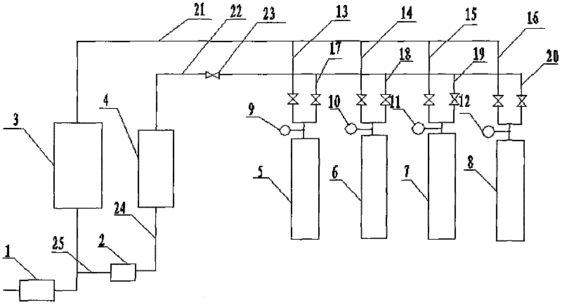
[0010] Step 1, initially all valves are closed;

[0011] Step 2, turn on the gas compressor 1, inflate the high-pressure gas storage tank 3, and turn off the gas compressor 1 after reaching the specified pressure;

[0012] Step 3, open the intake valve of the first test container 5, inflate the first test container 5, after reaching the test pressure, close the first test container 5 intake valve, and keep the pressure;

[0013] Step 4, when the pressure holding time of the first test container 5 is up, open the two-way valve of the first test container 5 and the two-way valve of the second test container 6 at the same time, so that the pressure in the first test container 5 is divided to the second test container. Two test containers 6, after the pressure difference in the first test container 5 and the second test container 6 reaches a preset value, close the intake valve of the second test container 6;

[0014] Step five, open the two-way valve of the third test container ...

no. 2 example

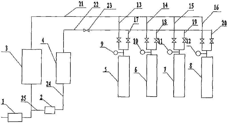
[0040] Test method of pressure vessel airtightness test device:

[0041] Step 1, initially all valves are closed;

[0042] Step 2, turn on the gas compressor 1, inflate the high-pressure gas storage tank 3, and turn off the gas compressor 1 after reaching the specified pressure;

[0043] Step 3, open the intake valve of the first test container 5, inflate the first test container 5, after reaching the test pressure, close the intake valve of the first test container 5, and keep the pressure;

[0044] Step 4, when the pressure holding time of the first test container 5 is up, open the two-way valves of all the test containers at the same time, so that the pressure in the first test container 5 is divided to other test containers. After the partial pressure is stable, close all the test containers. Two-way valve of the test vessel;

[0045] Step five, open the low-pressure gas storage tank valve 23, open the two-way valve of the first test container 5, pass the gas in the first ...


PUM


Abstract

The invention discloses an airtightness test device and method for a pressure container, belonging to the fields of equipment inspection technology and control technology. The device is characterized by comprising a gas compressor, a gas-driven pump, a high-pressure gas storage tank, a low-pressure gas storage tank and more than two tested containers, wherein each tested container is provided with a pressure indication device; a pipeline with a gas inlet valve is mounted on a gas inlet of each tested container; a pipeline with a two-way valve is mounted on a gas outlet of each tested container; the high-pressure gas storage tank is communicated with the low-pressure gas storage tank and multiple tested containers through pipelines; the tested container after pressure maintaining distributes pressure of the gas therein to the container which is not tested, and distributes pressure to the low-pressure gas storage tank; an outlet pipeline of the low-pressure gas storage tank is provided with the gas-driven pump; and the outlet pipeline of the low-pressure gas storage tank with the gas-driven pump is communicated with a gas inlet pipeline of the high-pressure gas storage tank. Through the invention, the utilization of high-energy gas can be improved, and the aims of saving energy and improving inspection efficiency are achieved.

Description

technical field [0001] The invention belongs to the field of inspection equipment technology and control technology, and relates to an airtightness test method for batch pressure vessels. Background technique [0002] All pressure vessels need to be tested for air tightness. The test gas injected into the pressure vessel has relatively high energy. In the past, the test device discharged the gas into the atmosphere after the test, which would cause great energy waste. The design of the device of the invention fully utilizes the high-pressure gas in the pressure vessel after the test, and realizes the circulation and continuous detection of multiple pressure vessels through an automatic control system. Patent 200920274829 realizes the semi-automatic control of the process and ensures the safety of the person and the container, but does not involve the use of high-pressure gas that has been compressed into the pressure container. Patent No. 200810013210 and Patent No. 2007100...

Claims


Application Information

Patent Timeline
IPC IPC(8): G01M3/32
Inventor 由宏新乔辉周一卉刘润杰
Owner DALIAN UNIV OF TECH
Why Eureka
Try Eureka