System and method for calibrating linear array camera based on laser scanner

A technology of laser scanner and line array camera, which is applied in the direction of instruments, image data processing, measuring devices, etc., can solve the problems of a large amount of computation and difficult to guarantee the calibration accuracy, and achieve the effect of reducing the computation amount and high calibration accuracy

Active Publication Date: 2012-02-01
CAPITAL NORMAL UNIVERSITY
View PDF4 Cites 14 Cited by
  • Summary
  • Abstract
  • Description
  • Claims
  • Application Information

AI Technical Summary

Problems solved by technology

At present, the three-dimensional measurement technology mainly obtains the image of the measured object through the line array camera, and further reconstructs the absolute three-dimensional coordinates of the measured object by calculating the internal orientation elements of the camera. The process of calculating the internal orientation elements of the camera is called Camera calibration, because the relative position between the line array camera and the target ob

Method used


Image

  • System and method for calibrating linear array camera based on laser scanner
  • System and method for calibrating linear array camera based on laser scanner
  • System and method for calibrating linear array camera based on laser scanner

Examples


Embodiment Construction

[0012] The present invention will be further described below in conjunction with the accompanying drawings and specific embodiments.

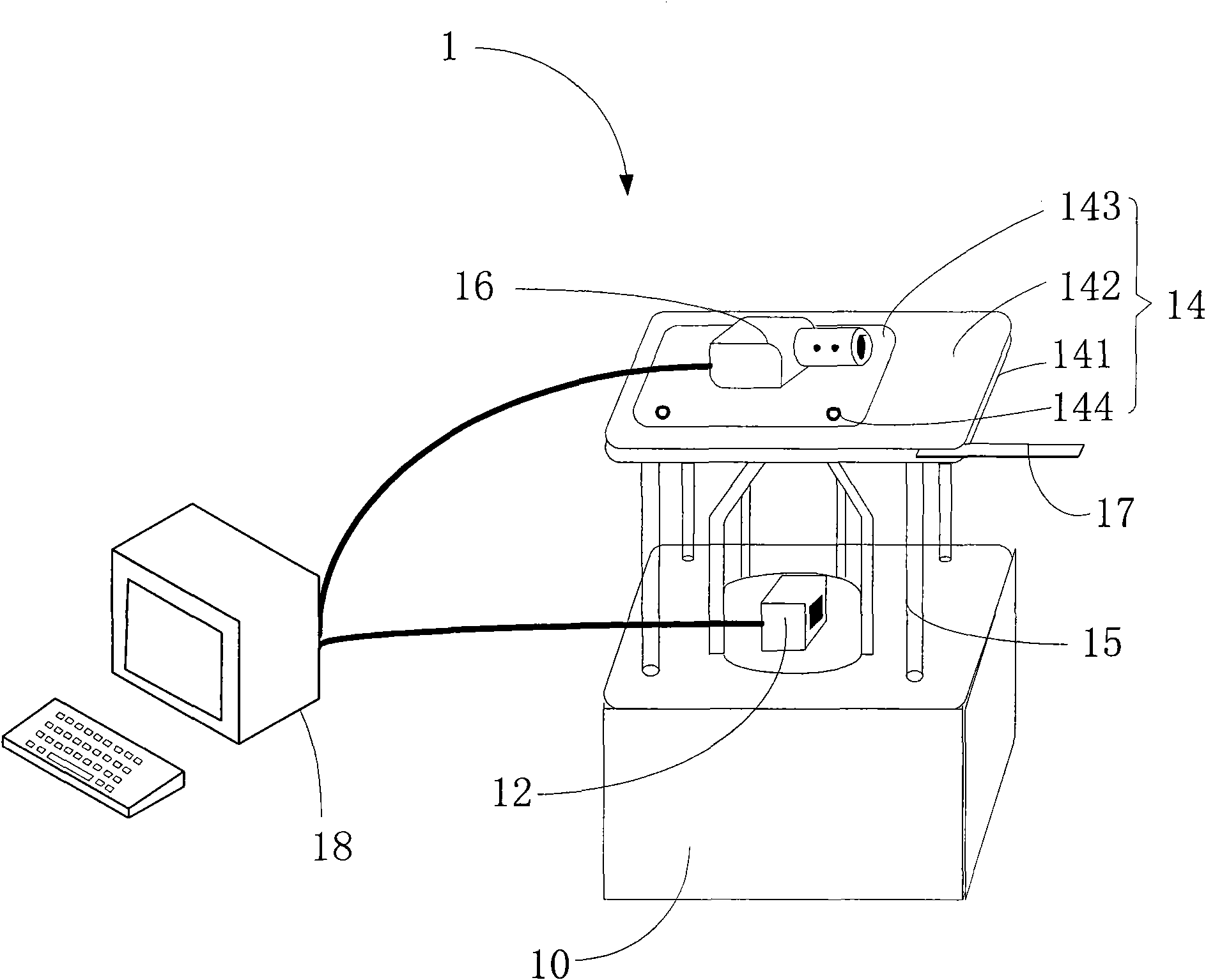
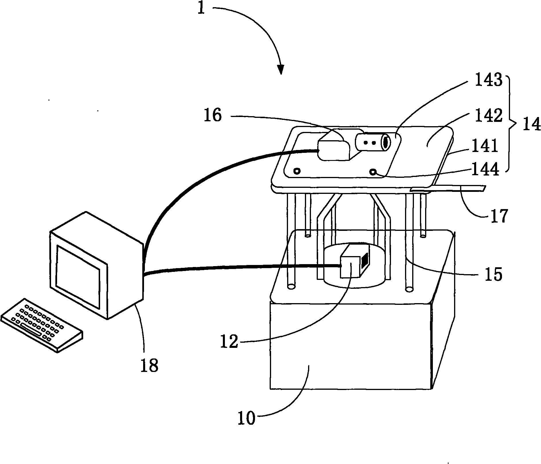
[0013] Please refer to figure 1 A preferred embodiment of the system 1 for calibrating a line scan camera based on a laser scanner in the present invention includes a carrying device 10, a laser scanner 12, a filter plate 14 and a resolution device 18, and the calibration line based on the laser scanner The array camera system 1 is used to calibrate the array camera 16, which is used to acquire an image of a measured target object during the three-dimensional measurement process.

[0014] The laser scanner 12, the filter plate 14 and the line scan camera 16 are all installed on the carrying device 12, wherein the laser scanner 12 is installed on the surface of the carrying device 10, and the vertical A bracket 15 is directly fixed, and the bracket 15 is fixed around the laser scanner 12 , and the filter plate 14 is fixed on the bracket 15 and ...


PUM


Abstract

The invention provides a system for calibrating a linear array camera based on a laser scanner, comprising a bearing device, a laser scanner and a resolver, wherein the laser scanner is arranged on the bearing device, and the bearing device is provided with a support which is used for fixing the linear array camera; the laser scanner is arranged below the linear array camera, the scanning direction of the laser scanner is parallel to the lens direction of the linear array camera, and nodes of the laser scanner and nodes of the linear array camera are in the same vertical straight line; the laser scanner scans to acquire point cloud data of a measured target object; the linear array camera takes pictures for positions scanned by the laser scanner so as to acquire image data of the measured target object; and the resolver receives the point cloud data and the image data, carries out characteristic matching on the received data and operates inner orientation elements of the linear array camera in accordance with the received data. The invention also provides a method for calibrating the linear array camera based on the laser scanner. The system and method provided by the invention can be used to reduce the workload of calibrating the linear array camera.

Description

technical field [0001] The invention relates to a method for calibrating a line array camera, in particular to a system and method for calibrating a line array camera based on a laser scanner. Background technique [0002] With the increasing popularity of 3D spatial information services, people have higher and higher requirements for the fidelity of virtual reality, and 3D measurement technology has attracted more and more attention. At present, the three-dimensional measurement technology mainly obtains the image of the measured object through the line array camera, and further reconstructs the absolute three-dimensional coordinates of the measured object by calculating the internal orientation elements of the camera. The process of calculating the internal orientation elements of the camera is called Camera calibration, because the relative position between the line array camera and the target object is constantly changing during dynamic shooting, the traditional camera c...

Claims


Application Information

Patent Timeline
IPC IPC(8): G06T7/00G01C25/00
Inventor 王留召宫辉力钟若飞刘先林
Owner CAPITAL NORMAL UNIVERSITY
Why Eureka
Try Eureka