Pluggable surge protector

A surge protector and plug-in technology, which is applied in the field of plug-in surge protectors, can solve problems such as structural threats, module falling off, and reducing the value of plug-in structures, achieving the effect of achieving convenience and reducing operating requirements

Active Publication Date: 2012-02-01
SEARI ELECTRIC TECH
View PDF5 Cites 12 Cited by
  • Summary
  • Abstract
  • Description
  • Claims
  • Application Information

AI Technical Summary

Problems solved by technology

The current products in the market usually have to use tools to pull out the module from the base, which affects the convenience of product maintenance and increases the workload of product maintenance and replacement.
[0012] In particular, when the space where the product is installed is small, it is impossible to pull out the module with commonly used tools such as a screwdriver, which reduces the value of the plug-in structure
[0013] In addition, there is another deadly structural threat in the plug-in structure for plug-in SPDs installed in places with vibration properties (such as in wind turbines)-the module may fall off from the base
The reason is that when the product is working in a vibration environment, the module in the plug-in SPD is subjected to vibration force in an indeterminate direction at a certain vibration frequency. When the vibration acceleration direction is consistent with the module’s pull-out direction, the vibration force at this time will be Acting directly on the plug-in parts, when the force value is greater than or close to the friction force of the connector in the plug-in part, or exists for a long time, it may cause the SPD module to fall off, reducing the safe working factor of the plug-in structure SPD

Method used


Image

  • Pluggable surge protector
  • Pluggable surge protector
  • Pluggable surge protector

Examples


Embodiment Construction

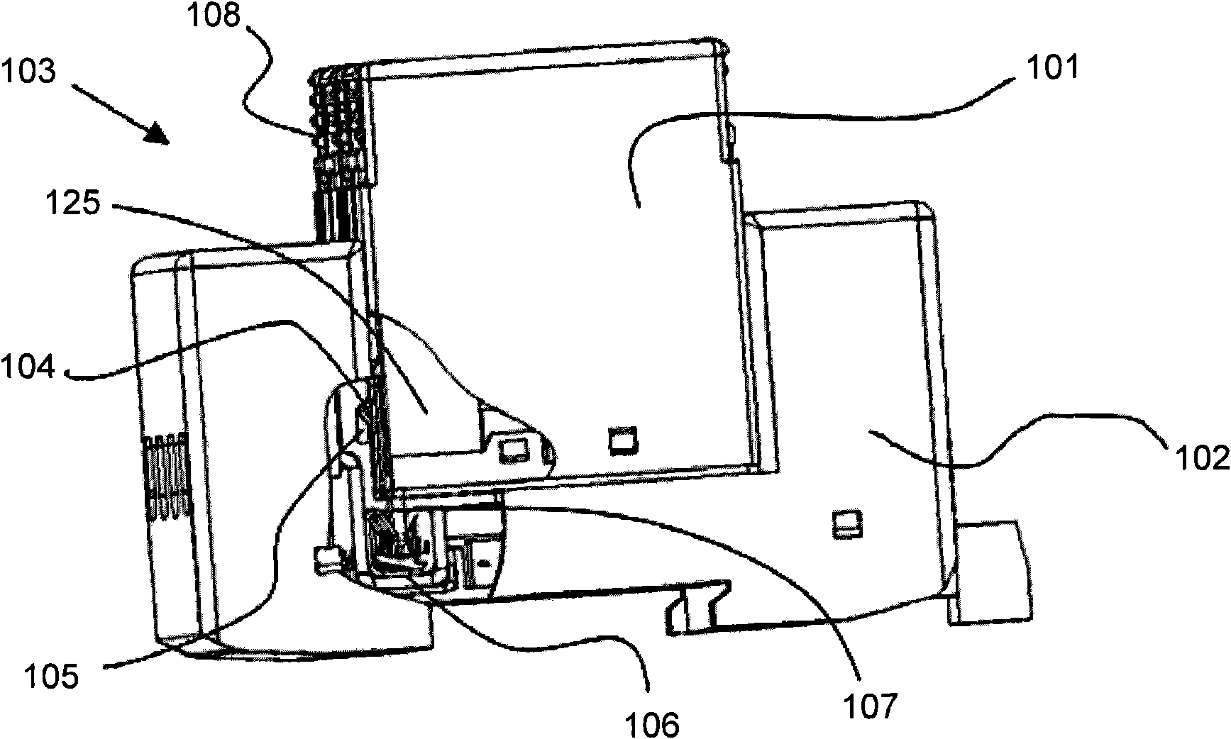
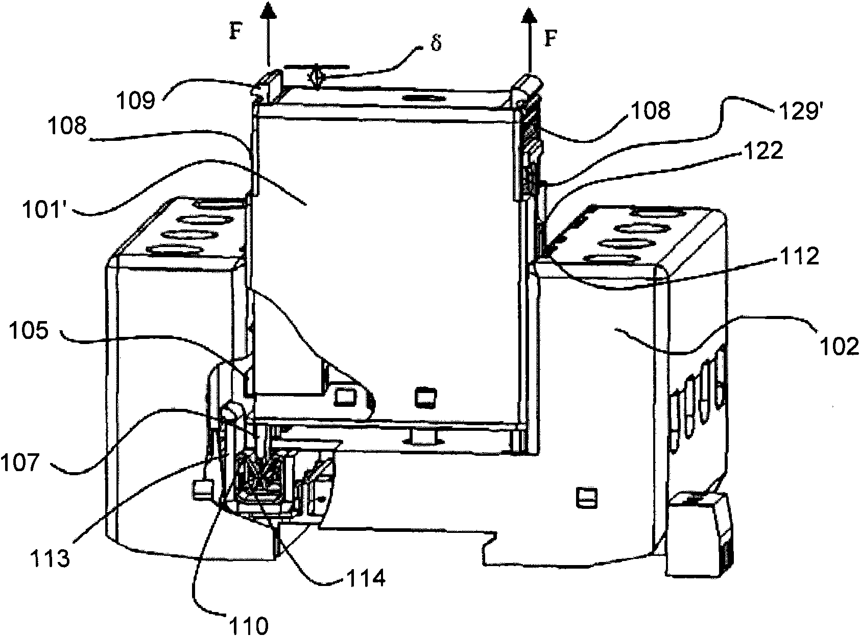
[0038] The invention discloses a plug-in surge protector, referring to figure 1 or figure 2 , the plug-in surge protector includes a plug-in module 101 and a base 102, and the plug-in module 101 is inserted into the base 102.

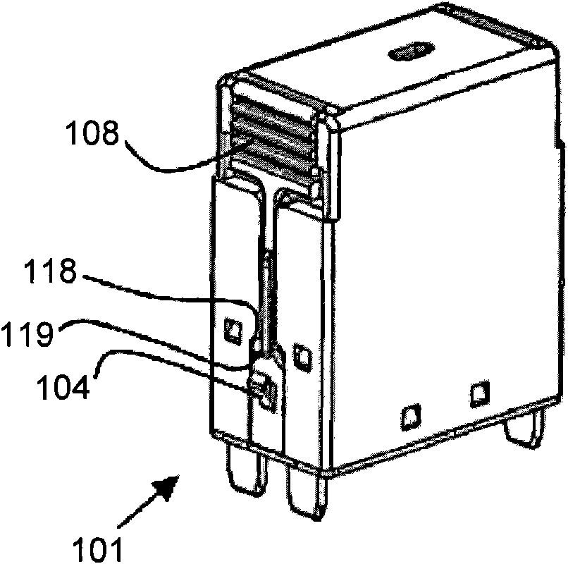
[0039]The plug-in module includes: a housing, an electrode 125 placed in the housing, a buckle 104 , a trip plate 109 arranged on both sides of the housing, and a pin 107 fixed on the bottom of the housing. The pin 107 is electrically connected to the electrode 125 .

[0040] The base 102 has an opening whose size and shape match the plug-in module 101, the plug-in module 101 is inserted into the opening of the base 102, the bottom of the opening has a plug-in structure 106, and the plug-in structure 106 cooperates with the pin 107 of the plug-in module 101; The side wall of the opening has a locking groove 105 , and the locking groove 105 is matched with the buckle 104 of the plug-in module 101 .

[0041] When the plug-in module 101 is inserted into...


PUM


Abstract

The invention discloses a pluggable surge protector, which comprises a plugging and unplugging module and a base, wherein the plugging and unplugging module is plugged into the base, and comprises a shell, an electrode arranged in the shell, a buckle, tripping plates arranged on the two sides of the shell and a pin fixed at the bottom of the shell; the pin is electrically connected with the electrode; the base has an opening with a size and a shape which are matched with those of the plugging and unplugging module; the plugging and unplugging module is plugged into the opening of the base; the bottom of the opening has a plugging and unplugging structure which is in fit with the pin; the sidewall of the opening is provided with a buckling groove which is in fit with the buckle; when the plugging and unplugging module is plugged into the base, the pin is plugged into the plugging and unplugging structure of the base to realize electric connection and energy storage, and the buckle is buckled in the buckling groove to fix the plugging and unplugging module in the base; and when the plugging and unplugging module is unplugged from the base, the tripping plates make the buckle withdraw from the buckling groove, the pin is plugged into the plugging and unplugging structure, and stored energy is released to push the pin out of the plugging and unplugging structure to realize the unplugging of the plugging and unplugging module from the base.

Description

technical field [0001] The invention relates to the field of low-voltage electrical appliances, and more specifically relates to a plug-in surge protector suitable for overvoltage protection and having a detachable protection module, wiring or / and installation base. Background technique [0002] With the continuous development of society, lightning protection has gradually become one of the issues that need to be considered by all walks of life, especially due to the overvoltage invasion caused by lightning, which has a wider impact on low-voltage power distribution systems. [0003] In order to ensure the normal operation of electrical equipment and reduce or eliminate the impact of lightning overvoltage, it is necessary to take comprehensive measures such as equipotential connection, cable burial, shielding, and installation of surge protectors (SPD). Among them, SPD has been It has become one of the routine and important lightning protection measures in the low-voltage po...

Claims


Application Information

Patent Timeline
Patent Type & Authority Applications(China)
IPC IPC(8): H02H9/04H01R13/633H01R13/639
Inventor 许年生尹天文王碧云刘明东颜沧苇曹阳
Owner SEARI ELECTRIC TECH
Why Eureka
Try Eureka