Image-capturing optical system, image-capturing optical device, and digital equipment
A photographic optical system and optical image technology, applied in the field of photographic optical systems, can solve problems such as high-pixel imaging components and insufficient thinning of optical structures, etc.
- Summary
- Abstract
- Description
- Claims
- Application Information
AI Technical Summary
Problems solved by technology
Method used
Image

Examples
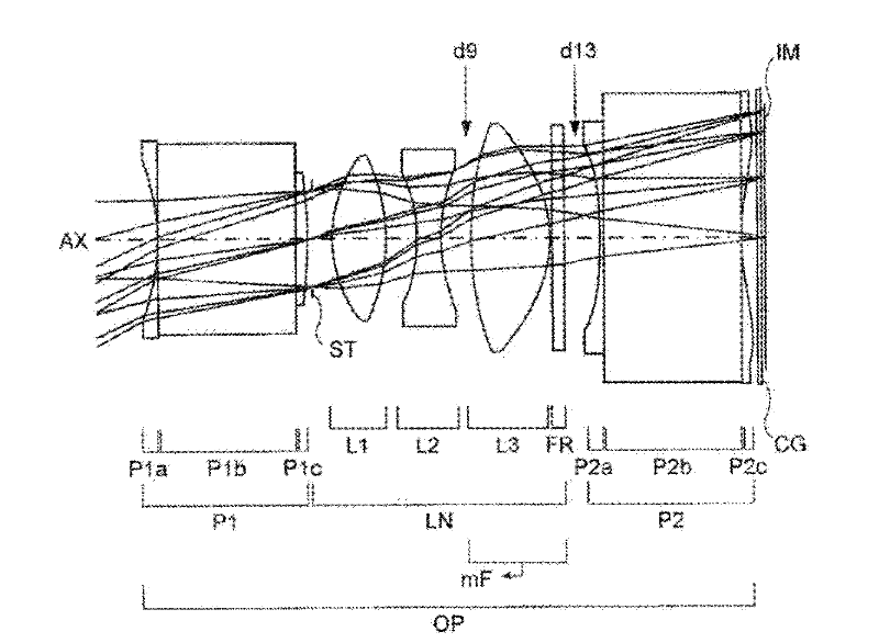
Embodiment 1
[0160] Unit: mm
[0161] surface data
[0162] face number r d nd vd
[0163] object plane ∞d0
[0164] 1*-5.117 0.000 1.525 56.45
[0165] 2∞3.433 1.525 56.45
[0166] 3∞0.298 1.525 56.45
[0167] 4*-9.386 0.112
[0168] 5 (stop) ∞0.500
[0169] 63.500 1.330 1.531 49.33
[0170] 7-5.000 0.787
[0171] 8*-4.857 0.600 1.607 27.10
[0172] 9*4.054 d9
[0173] 10*9.611 1.975 1.532 56.57
[0174] 11*-3.418 0.050
[0175] 12∞0.300 1.517 64.17
[0176] 13∞d13
[0177] 14*-18.247 0.100 1.607 27.10
[0178] 15∞3.418 1.607 27.10
[0179] 16*6.016 0.400
[0180] 17∞0.100 1.517 64.17
[0181] 18∞0.100
[0182] Image plane ∞
[0183] Aspheric Data
[0184] side 1
[0185] K=0.0
[0186] A4=3.4946E-03
[0187] A6=-9.8255E-05
[0188] A8=3.3987E-06
[0189] A10=9.6167E-08
[0190] side 4
[0191] K=0.0
[0192] A4=4.4700E-03
[0193] A6=1.7029E-04
[0194] A8=-3.1054E-05
[0195] A10=3.5086E-05
[0196] side 8
[0197] K=0.0
[0198] A4=-1.3095E-02
[0199...
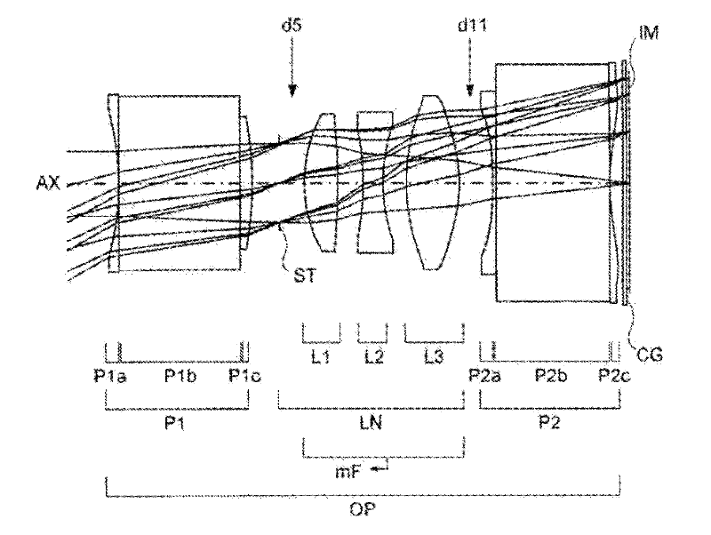
Embodiment 2
[0244] Unit: mm
[0245] surface data
[0246] face number r d nd vd
[0247] object plane ∞d0
[0248] 1*-7.934 0.000 1.768 49.23
[0249] 2∞3.620 1.768 49.23
[0250] 3∞0.355 1.768 49.23
[0251] 4*-10.540 0.805
[0252] 5 (stop) ∞d5
[0253] 64.349 1.012 1.815 43.33
[0254] 7-20.408 0.750
[0255] 8-8.931 0.600 1.804 24.32
[0256] 95.412 0.700
[0257] 10*6.647 1.584 1.525 56.45
[0258] 11*-4.709 d11
[0259] 12*-14.256 0.100 1.607 27.60
[0260] 13∞3.384 1.607 27.60
[0261] 14*6.813 0.400
[0262] 15∞0.100 1.517 64.17
[0263] 16∞0.100
[0264] Image plane ∞
[0265] Aspheric Data
[0266] side 1
[0267] K=0.0
[0268] A4=9.0280E-04
[0269] A6=2.3895E-05
[0270] A8=-4.7532E-06
[0271] A10=3.3500E-07
[0272] side 4
[0273] K=0.0
[0274] A4=1.3480E-03
[0275] A6=-1.0479E-04
[0276] A8=2.9829E-05
[0277] A10=-1.9600E-06
[0278] side 10
[0279] K=0.0
[0280] A4=1.3224E-04
[0281] A6=3.6821E-04
[0282] A8=1.2316E-05
[0283]...
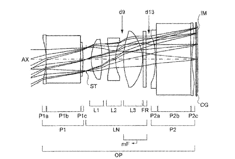
Embodiment 3
[0314] Unit: mm
[0315] surface data
[0316] face number r d nd vd
[0317] object plane ∞d0
[0318] 1*-5.934 0.000 1.525 56.45
[0319] 2∞3.389 1.849 33.11
[0320] 3∞0.255 1.525 56.45
[0321] 4*-13.149 0.313
[0322] 5 (stop) ∞0.500
[0323] 63.885 1.060 1.701 47.99
[0324] 7-11.520 0.741
[0325] 8*-11.141 0.600 1.607 27.10
[0326] 9*3.524 d9
[0327] 10*7.519 1.884 1.525 56.45
[0328] 11*-3.727 0.050
[0329] 12∞0.300 1.517 64.17
[0330] 13∞d13
[0331] 14*-11.880 0.100 1.583 29.90
[0332] 15∞3.398 1.850 40.00
[0333] 16∞0.100 1.583 29.90
[0334] 17*6.263 0.400
[0335] 18∞0.100 1.517 64.17
[0336] 19∞0.100
[0337] Image plane ∞
[0338] Aspheric Data
[0339] side 1
[0340] K=0.0
[0341] A4=3.4627E-03
[0342]A6=-1.0819E-04
[0343] A8=5.6463E-07
[0344] A10=1.6782E-07
[0345] side 4
[0346] K=0.0
[0347] A4=4.0674E-03
[0348] A6=-7.0872E-04
[0349] A8=3.4454E-04
[0350] A10=-6.1112E-05
[0351] side 8
[0352] K=0.0...
PUM
 Abstract
Description
Claims
Application Information