Pin-forming mold for integrated circuits

A technology for forming molds and integrated circuits, which is applied in the field of integrated circuit compression molding, can solve the problems of mandrel and roller sticking, changing back to sliding friction forming, and rollers cannot roll, etc., to achieve convenient molding size, improve quality, and avoid sticking Effect

Inactive Publication Date: 2012-02-08
TONGLING SANJIA YAMADA TECH
View PDF5 Cites 15 Cited by
  • Summary
  • Abstract
  • Description
  • Claims
  • Application Information

AI Technical Summary

Problems solved by technology

However, the single-roller forming method is still not a pure rolling friction method, especially the mandrel and the roller will be stuck after a long period of use, and the roller cannot roll when it is stu

Method used


Image

  • Pin-forming mold for integrated circuits
  • Pin-forming mold for integrated circuits
  • Pin-forming mold for integrated circuits

Examples


Embodiment Construction

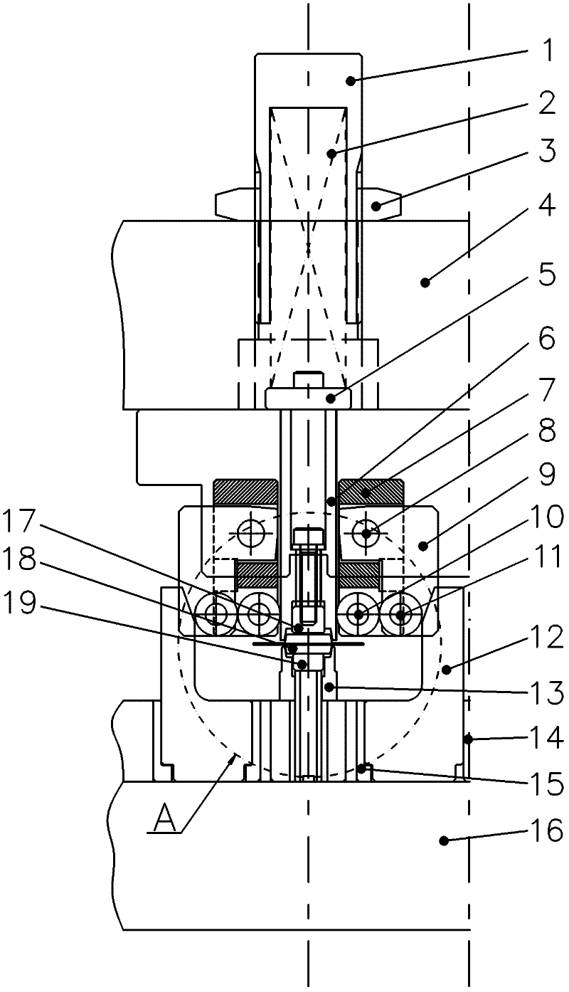
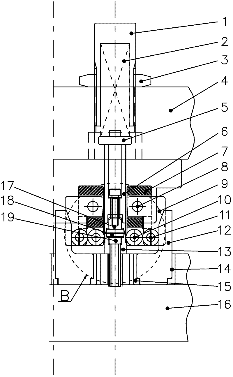
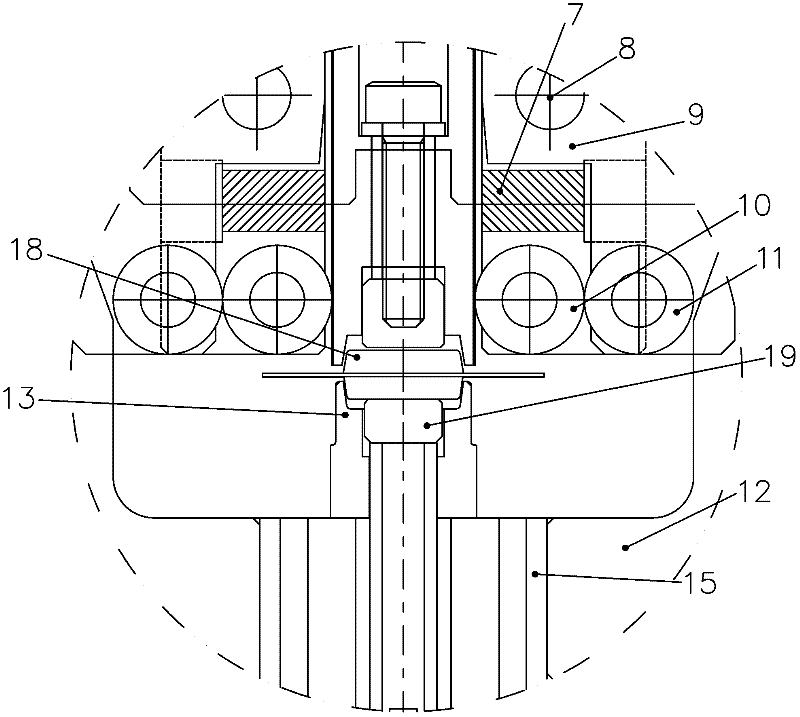
[0030] Such as Figure 1~4 As shown, a pin molding die for integrated circuits, this mold includes a fixing device for pressing the product 18 and its pins to be formed, and the two sides of the fixing device are provided with pins for forming the pins A conjugate roller device, the side of the conjugate roller device away from the fixing device is provided with a wedge device for guiding the conjugate roller device to work.

[0031] Preferably, the fixing device includes a forming concave film 13 for erecting the product to be formed 18, and also includes a pressing block 17 pressed against the upper side of the product to be formed 18 and a top material against the lower side of the product to be formed 18 Block 19; the binder block 17 is penetrated in the binder plate 6, and the binder block 17 forms a sliding fit with the binder plate 6; the lower side of the binder plate 6 is provided with a leg pressed against the pin ; The upper side of the pressing plate 6 extends upw...


PUM


Abstract

The invention belongs to the field of press-forming integrated circuits and particularly relates to a pin-forming mold for DIP (Dual Inline Package)/IDF (Intermediate Distributing Frame) package integrated circuits. The mold comprises a fixing device which is used for holding down a product to be formed and pins of the product; conjugate roller wheel devices which are used for enabling pins to be formed are respectively arranged at two sides of the fixing device; and a taper wedge device which is used for guiding the conjugate roller wheel device to work is arranged at one side of each of the conjugate roller wheel devices far away from the fixing device. The mold is made from a pair of conjugate roller wheels, i.e. main roller wheels and auxiliary roller wheels, which can swing; when the pins are formed, the main roller wheels and the auxiliary roller wheels generate conjugate movement, i.e. the main roller wheels and the auxiliary roller wheels mutually rotate in opposite directions so as to ensure that the pins of the product are formed by means of pure rolling, thus the quality of the product can be greatly improved; and meanwhile, the phenomenon of clamping stagnation generated between a mandrel and roller wheels in a single-roller wheel forming manner can be avoided.

Description

technical field [0001] The invention belongs to the field of integrated circuit pressing and molding, and in particular relates to a lead molding die for integrated circuits packaged in DIP / IDF type. Background technique [0002] DIP packaging, also known as dual in-line packaging technology, English is Dual In-line Package, is the simplest packaging method, and most small and medium-sized integrated circuits (ICs) use this packaging form. The traditional and more general DIP package lead forming method is rigid forming method or single roller forming method. Initially, the rigid forming method was adopted in the industry. The structure of the rigid forming method is simple, and the forming punch and die are fixed. Since the rigid forming method uses the punch to slide on the surface of the pin to form the pin, It will inevitably lead to scratches on the tin-plated layer on the surface of the pins, especially after long-term use, due to the accumulation of tin layer on the ...

Claims


Application Information

Patent Timeline
IPC IPC(8): B21F1/00
Inventor 李庆生
Owner TONGLING SANJIA YAMADA TECH
Why Eureka
Try Eureka