Thrust spring support for limiting rolling and slipping of rolling shaft

A technology of sliding limit and thrust spring, which is applied in the direction of construction and building construction, and can solve the problems of rod damage in the area near the support and unsafe overall structure, etc.

Active Publication Date: 2014-02-19
SHANGHAI ARCHITECTURAL DESIGN & RES INST +1
View PDF5 Cites 0 Cited by
  • Summary
  • Abstract
  • Description
  • Claims
  • Application Information

AI Technical Summary

Problems solved by technology

At present, the elastic bearings at home and abroad are mostly realized by the shear deformation of rubber and the overall sliding of the bearing. However, if the vertical reaction force of the bearing is large and there is a large horizontal thrust, due to the increase of friction Large, it is impossible to realize sliding under real conditions, which will inevitably lead to the damage of the rods in the area near the support, which will lead to the unsafety of the overall structure

Method used


Image

  • Thrust spring support for limiting rolling and slipping of rolling shaft
  • Thrust spring support for limiting rolling and slipping of rolling shaft

Examples


Embodiment Construction

[0010] In order to better understand the technical content of the present invention, specific embodiments are given together with the attached drawings for description as follows.

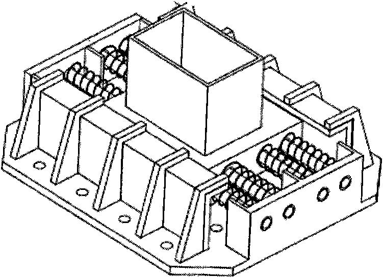
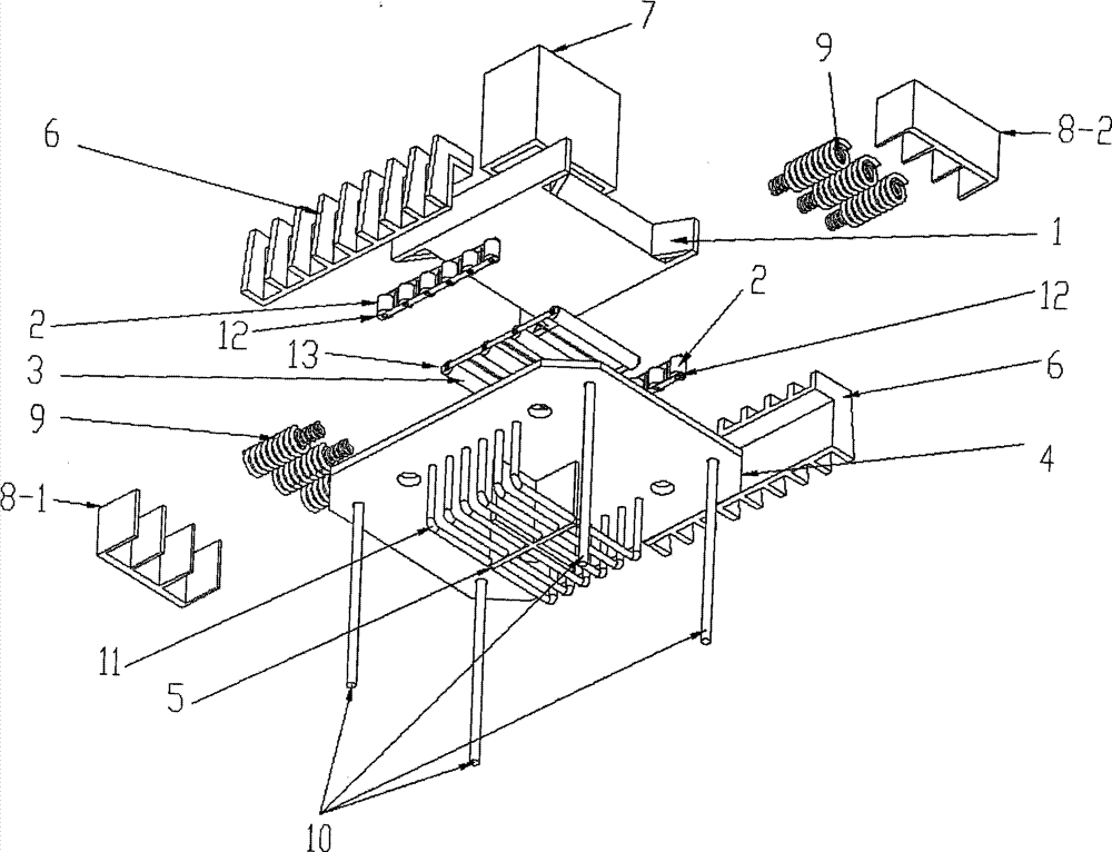
[0011] Please refer to figure 1 and figure 2 , figure 1 Shown is a schematic diagram of the structure of the roller shaft rolling slip limit thrust spring support in a preferred embodiment of the present invention, figure 2 Shown is a schematic diagram of the exploded structure of the roller shaft rolling slip limit thrust spring support in a preferred embodiment of the present invention. The present invention proposes a roller shaft rolling slip limit thrust spring support, which includes a support bottom plate 4, a support card seat 6, a short column lower box 1 and a support short column 7, and the support card seat 6 The short column lower box 1 is snapped onto the support bottom plate 4, the support short column 7 is arranged on the short column lower box 1, and the front and rear sides o...


PUM


Abstract

The invention provides a thrust spring support for limiting rolling and slipping of a rolling shaft, which comprises a support bottom plate, a support clamping seat, a short-column lower box body and a support short column, wherein the support clamping seat clamps the short-column lower box body on the support bottom plate; the support short column is arranged on the short-column lower box body; the front side and the rear side of the short-column lower box body are respectively provided with springs corresponding to spring baffles arranged at the two sides of the support bottom plate; the left side, the right side and the bottom part of the short-column lower box body are respectively provided with side-surface rolling shafts and bottom-surface rolling shafts; the side-surface rolling shafts are arranged among the left side and the right side of the short-column lower box body and the support clamping seat; and the bottom-surface rolling shafts are arranged between the bottom part of the short-column lower box body and the support bottom plate. According to the thrust spring support provided by the invention, the friction force is less, stable and reliable elastic stiffness is realized by a reliable mechanism, and reliable limiting and return devices are provided.

Description

technical field [0001] The invention relates to the field of building structure design, and in particular to a rolling and slipping limit thrust spring support of a roller shaft. Background technique [0002] In the design of super-long building structures, expansion joints cannot be set due to architectural requirements. Or because the thermal expansion coefficient of the material used in the structure is large, it will bring huge temperature stress. In both cases, safe structural design should consider the release of temperature stress. At present, the elastic bearings at home and abroad are mostly realized through the shear deformation of rubber and the overall sliding of the bearing. However, if the vertical reaction force of the bearing is large and there is a large horizontal thrust, due to the increase of friction Large, unable to realize sliding under real conditions, it will inevitably lead to damage to the rods in the area near the support, which will lead to the...

Claims


Application Information

Patent Timeline
Patent Type & Authority Patents(China)
IPC IPC(8): E04B1/36
Inventor 李亚明周晓峰张良兰顾龙国康方阳
Owner SHANGHAI ARCHITECTURAL DESIGN & RES INST
Why Eureka
Try Eureka