Engine cooling apparatus

A cooling device and engine technology, which is applied in the cooling of the engine, engine components, machines/engines, etc., can solve the problems of easy knocking, easy cavitation, and reduced water pump pressure, so as to suppress cavitation and knocking Effect

Inactive Publication Date: 2012-02-08
YAMADA SEISAKUSHO KK
View PDF1 Cites 10 Cited by
  • Summary
  • Abstract
  • Description
  • Claims
  • Application Information

AI Technical Summary

Problems solved by technology

[0008] In the structure and control of Patent Document 1, when the flow rate of cooling water necessary for cooling the engine in the middle engine rotation area is ensured, the cooling water flowing in the second bypass passage in the high-speed engine rotation area The flow rate of the pump increases, so the pressure in the flow path on the suction side of the pump decreases, and cavitation may easily occur
On the other hand, if the discharge flow rate of the water pump is set to be slightly small so that cavitation does not occur in the high-speed engine rotation range, the engine may easily knock under the high-load operation state in the low-speed rotation range, resulting in The problem of reduction in engine output

Method used


Image

  • Engine cooling apparatus
  • Engine cooling apparatus
  • Engine cooling apparatus

Examples


Embodiment Construction

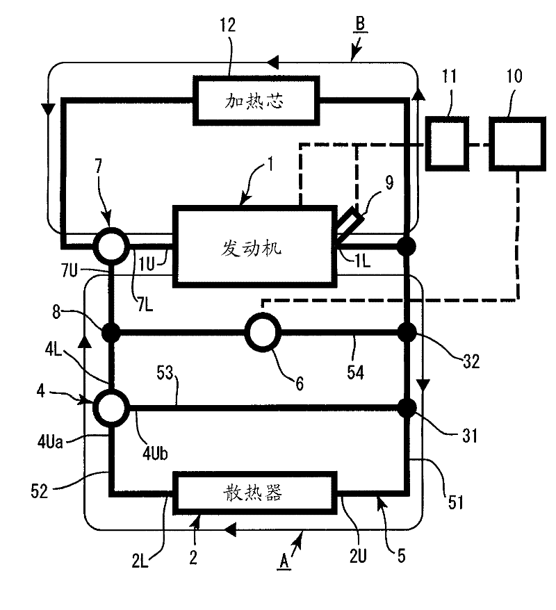
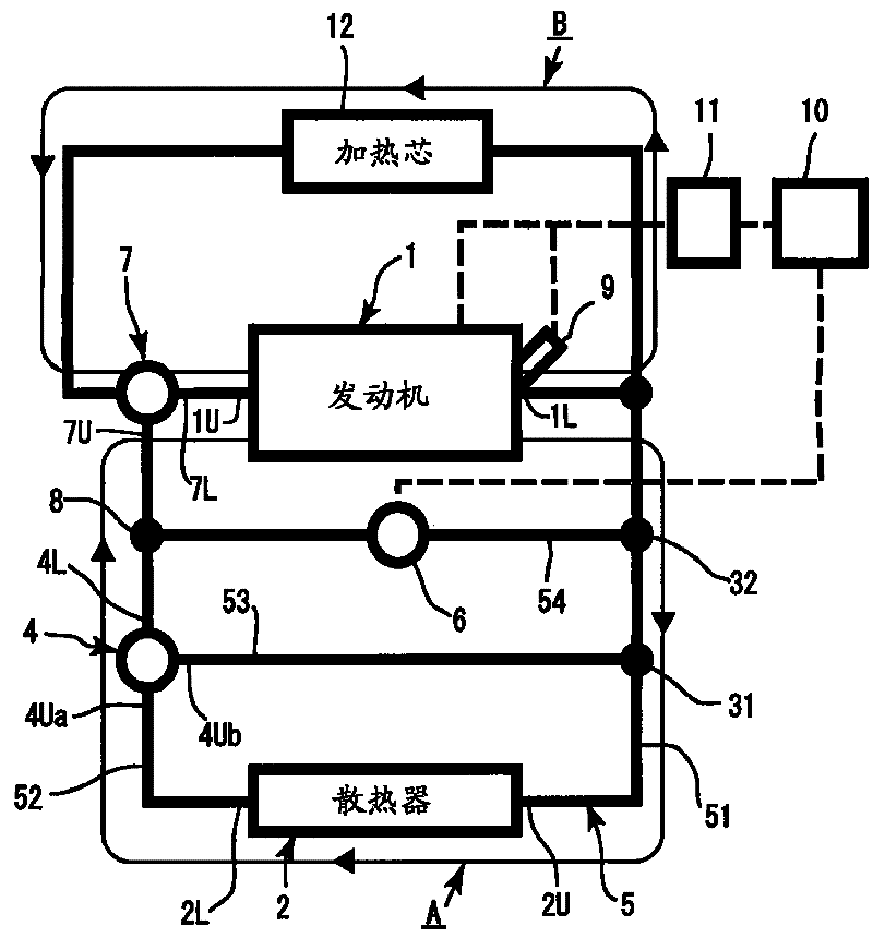
[0020] Embodiments of the present invention will be described below based on the drawings. The present invention is a circuit in which cooling water circulates between the engine 1 and the radiator 2, and is mainly composed of a main cooling water circuit A, a first bypass passage 53, and a second bypass passage 54, and, in addition to these circuits, A heating circuit B having a flow path passing through the engine 1 and a heater core 12 included in the flow path is added together with the main cooling water circuit A described above.

[0021] figure 1 The cooling water circuit of the present invention is shown. Hereinafter, in the description, for parts such as radiator 2 and thermostat 4 in the cooling water circuit, the side where the cooling water flows into the parts is referred to as the upstream side, and "U" is added to the reference numerals of the parts, The side where the cooling water flows out from the part is called the downstream side, and "L" is added to the...


PUM


Abstract

An engine cooling apparatus that is capable of suppressing cavitation in a high rotation region while achieving an increase in a circulation flow rate of cooling water in a low / medium rotation region. The engine cooling apparatus includes: a main cooling water circuit (A) that circulates the cooling water between an engine (1) and a radiator (2); a branch portion provided between the engine (1) and the radiator (2); a thermostat (4); temperature detecting means (9); a first bypass flow passage (53); a second bypass flow passage (54) that connects the engine to the branch portion; a control valve (6); a bypass convergence portion (8); a water pump (7); valve opening control means (10); and engine rotation speed detecting means (11). When the temperature of the cooling water is lower than the predetermined temperature, the first bypass flow passage (53) is set in a cooling water circulation state, when the temperature of the cooling water is higher than the predetermined temperature, the first bypass flow passage (53) is set in a cooling water non-circulation state. When the engine rotation speed is lower than a predetermined rotation speed, the control valve (6) is controlled to a fully open state, and when the engine rotation speed is higher than a predetermined rotation speed, the control valve (6) is controlled to a fully closed direction from the fully open state.

Description

technical field [0001] The invention relates to a cooling device of an engine which suppresses cavitation in a high-speed rotation region and realizes an increase in the circulating flow rate of cooling water in a low- and medium-speed rotation region. Background technique [0002] In the cooling water circuit in which the cooling water flowing out of the engine is provided with a bypass circuit that bypasses the radiator and returns to the engine, it is known that two bypass circuits are arranged in parallel, and one of the two bypass circuits is A valve is installed in the circuit on the side, and the valve is opened when the engine rotates at a high speed to reduce the flow resistance, thereby preventing the cooling water circuit from cavitation. [0003] For example, in Patent Document 1 (Japanese Unexamined Patent Publication No. 2007-100659 ), two first bypass passages 7 and second bypass passages 10 are connected in parallel so as to bypass the radiator 2 . An electr...

Claims


Application Information

Patent Timeline
Patent Type & Authority Applications(China)
IPC IPC(8): F01P7/16
CPCF01P2060/08F01P7/165F01P2025/64F01P7/167
Inventor 小屋敷秀彦小林刚三国贵弘
Owner YAMADA SEISAKUSHO KK
Why Eureka
Try Eureka