
Vacuum protective valve

A vacuum protection and vacuum technology, applied in valve details, safety valves, balance valves, etc., can solve the problems of reduced response speed of vacuum terminals, broken vacuum, small flow rate, etc., to achieve improved reliability, strong adaptability, and easy maintenance Effect

Active Publication Date: 2012-02-08
SHANGHAI MICRO ELECTRONICS EQUIP (GRP) CO LTD
View PDF5 Cites 8 Cited by
  • Summary
  • Abstract
  • Description
  • Claims
  • Application Information

AI Technical Summary

Problems solved by technology

[0006] The present invention aims to solve the problem in the prior art that the flow rate of the vacuum system is too small, the response speed of the vacuum terminal is reduced under the working conditions of vacuum holding and vacuum breaking due to the avoidance of vacuum crosstalk, and even affects the working conditions of breaking vacuum and high pressure purge. and other technical issues

Method used


Image

  • Vacuum protective valve
  • Vacuum protective valve
  • Vacuum protective valve

Examples


Embodiment Construction

[0044] In order to make the technical features of the present invention more comprehensible, specific embodiments are given below in conjunction with the accompanying drawings to further describe the present invention.

[0045] See Figure 4 , which is a schematic structural diagram of a vacuum protection valve provided by an embodiment of the present invention. The vacuum protection valve includes: an upper valve body 401; a lower valve body 403 fitted with the upper valve body; an adjusting bolt 404 connected with the lower valve body 403; a valve core 407 placed in the lower valve body 401, and fit with the adjusting bolt 404; the movable valve seat 408 is placed in the lower valve body 403, and abuts against the valve core 407; the transmission rod 410 is placed in the upper valve body 401 and the movable valve seat 408 , and abut against the valve core 407 ; The adjusting bolt 404 is screwed into the internal thread of the through hole at the bottom of the lower valve b...


PUM


Abstract

The invention discloses a vacuum protective valve. The valve comprises an upper valve body (401), a lower valve body (403), an adjusting bolt (404), a valve core (407), a movable valve seat (408), a transmission rod (410) and a pressure sensing cavity (412), wherein the lower valve body (403) is sleeved with the upper valve body (401); the adjusting bolt (404) is connected with the lower valve body (403); the valve core (407) is arranged in the lower valve body (403) and sleeved with the adjusting bolt (404); the movable valve seat (408) is arranged in the lower valve body (403) and pressed against the valve core (407); the transmission rod (410) is arranged in the upper valve body (401) and the movable valve seat (408) and pressed against the valve core (407); and the pressure sensing cavity (412) is connected to the upper valve body (401) and pressed against the transmission rod (410).

Description

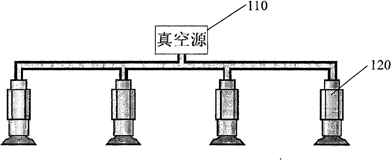
technical field [0001] The invention relates to the technical field of vacuum suction, and in particular to a vacuum protection valve. Background technique [0002] Vacuum components such as suction cups are widely used in workpiece holding and other occasions. In this occasion, a centralized vacuum system is usually used, such as figure 1 As shown, several suction cups 120 share one vacuum source 110, thereby improving the utilization efficiency of the vacuum air source. However, the vacuum system has the potential problem of vacuum crosstalk: that is, due to the aging of the suction cup, the damage of the workpiece, the wrong position of the workpiece, etc., a certain vacuum suction cup in the system fails, and when it is directly connected to the outside atmosphere under the suction working condition, it will cause The vacuum in the vacuum supply line has dropped significantly. Since the failed suction cup shares the vacuum with other vacuum suction cups, the drop in sy...

Claims


Application Information

Patent Timeline
Patent Type & Authority Applications(China)
IPC IPC(8): F16K31/126F16K17/00
Inventor 覃峰陈勇辉聂宏飞赵滨于文忠李其涛
Owner SHANGHAI MICRO ELECTRONICS EQUIP (GRP) CO LTD
Learn More