Liquid burst testing device

A test device, liquid explosion technology, applied in the direction of measuring device, using stable tension/pressure test material strength, instruments, etc., can solve the problems of inconvenient use, liquid leakage, costly materials, etc., to improve the convenience of use performance, prevent liquid leakage, and improve the sealing effect

Inactive Publication Date: 2012-02-08
HUZHOU IRON FORCE METAL PROD
View PDF6 Cites 0 Cited by
  • Summary
  • Abstract
  • Description
  • Claims
  • Application Information

AI Technical Summary

Problems solved by technology

[0004] 1. The sealing effect is not good: only by welding the inside of the hollow pipe 90 to form a closed space, it is easy to cause the hollow pipe 90 to be in contact with the first sealing member 91 and the second seal 91 due to the negligence of the welder or incomplete welding. There may still be a gap between the two seals 92, so that the liquid injected into the hollow pipe 90 may accidentally leak out, which will relatively affect the test results
[0005] 2. Poor convenience of use: because the first seal 91 and the second seal 92 must be welded to the opposite ends of the hollow pipe 90 in advance before the test operation, the test operation is quite cumbersome and time consuming and inconvenient to use
[0006] 3. Waste of material: because the first sealing member 91 and the second sealing member 92 are welded to the hollow pipe 90, therefore, after the test operation is completed, the first sealing member 91 and the second sealing member 92 must be separated from the bursting The hollow pipe fittings 90 are discarded together. As a result, a large amount of materials must be spent during the test operation, which causes a considerable burden on the user.
[0007] To sum up, the existing liquid explosion test device 9 generally still has many shortcomings such as poor sealing effect, poor convenience of use and waste of materials, so it is necessary to further improve it

Method used


Image

  • Liquid burst testing device
  • Liquid burst testing device
  • Liquid burst testing device

Examples


Embodiment 1

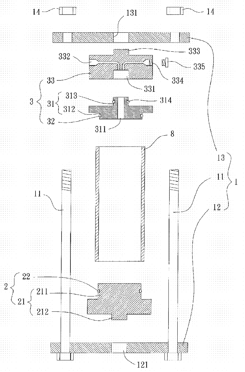
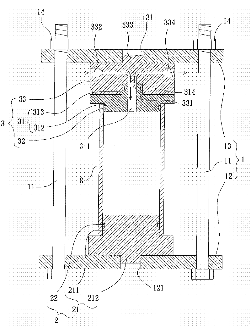
[0031] Such as figure 2 and image 3 As shown, the liquid explosion test device of the preferred embodiment of the present invention comprises a frame body 1, a first sealing assembly 2 and a second sealing assembly 3, and the first sealing assembly 2 and the second sealing assembly 3 are arranged on The frame body 1.

[0032] The frame body 1 is mainly used to carry the first sealing component 2 and the second sealing component 3 . In this embodiment, the frame body 1 includes several pillars 11 , a first splint 12 and a second splint 13 , and the several pillars 11 are arranged between the first splint 12 and the second splint 13 . Wherein, the distance between the first splint 12 and the second splint 13 can be adjusted arbitrarily according to the usage requirements, and the first splint 12 and the second splint 13 can be respectively fixed by several positioning components 14 . In addition, the first clamping plate 12 can also be provided with a first positioning port...


PUM


Abstract

The invention discloses a liquid burst testing device, which comprises: a frame body which is provided with a plurality of pillars, a first clamping plate and a second clamping plate, wherein the plurality of pillars are disposed between the first clamping plate and the second clamping plate; a first sealing assembly which is provided with a first plug body, wherein the first plug body is disposed on the first clamping plate of the frame body; and a second sealing assembly which is provided with a second plug body and an adapter piece, wherein the adapter piece is disposed on the second clamping plate of the frame body; the second plug body is connected with the adapter piece, and the second plug body is provided with a liquid channel. The technical scheme can effectively prevent liquid from leaking, and thus realize the improvement of sealing effect.

Description

technical field [0001] The present invention relates to a liquid explosion test device, in particular to a liquid explosion test device with good sealing effect. Background technique [0002] Such as figure 1 As shown, a kind of existing liquid explosion testing device 9, mainly is that a first sealing member 91 and a second sealing member 92 are respectively welded and combined on the opposite two ends of a hollow pipe 90, so that the inside of the hollow pipe 90 forms an airtight seal. space. In this way, during the test operation, the liquid is continuously injected into the hollow pipe 90 through the liquid inlet 911 of the first sealing member 91, and at the same time, it can be known whether the liquid has been filled through a liquid outlet 912 The hollow pipe 90 . Thereby, the inner wall of the hollow pipe 90 is subjected to the pressure of the liquid, and when the hydraulic pressure that the hollow pipe 90 can bear reaches the limit and bursts, the structural str...

Claims


Application Information

Patent Timeline
IPC IPC(8): G01N3/12G01N3/02
Inventor 陈清禄
Owner HUZHOU IRON FORCE METAL PROD
Why Eureka
Try Eureka