
Camera and operation method

An operation method and camera technology, applied in the field of digital cameras, can solve the problems of increased weight, volume and manufacturing cost of the shading mechanism, inability to effectively solve the interference effect, general camera operation method and no camera, etc.

Inactive Publication Date: 2012-02-08
ABILITY ENTERPRISE CO LTD
View PDF6 Cites 0 Cited by
  • Summary
  • Abstract
  • Description
  • Claims
  • Application Information

AI Technical Summary

Problems solved by technology

However, the shielding mechanism adds weight, bulk and manufacturing cost
[0003] In view of the fact that traditional digital cameras cannot effectively solve the interference effect, it is urgent to propose a novel digital camera that is not affected by interference phenomena such as slashes
[0004] This shows that above-mentioned existing digital camera obviously still has inconvenience and defect in camera operation method, camera structure and use, and urgently needs to be further improved
In order to solve the above-mentioned problems, the relevant manufacturers have tried their best to find a solution, but no suitable design has been developed for a long time, and the general camera operation method and camera have no suitable method and structure to solve the above-mentioned problems. This is obviously a problem that relevant industry players are eager to solve

Method used


Image

  • Camera and operation method
  • Camera and operation method
  • Camera and operation method

Examples


Embodiment Construction

[0031] In order to further explain the technical means and effects of the present invention to achieve the intended purpose of the invention, the specific implementation, steps, structure, and features of the camera and its operating method proposed according to the present invention will be described below in conjunction with the accompanying drawings and preferred embodiments. And its effect, detailed description is as follows.

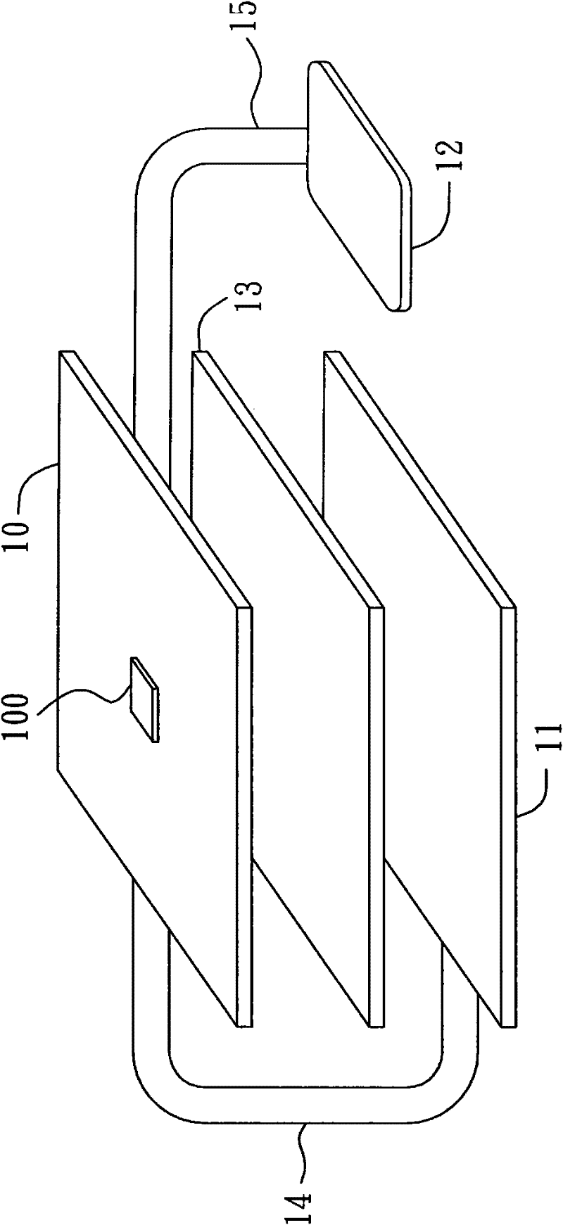
[0032] figure 1 A schematic composition diagram of a digital camera according to an embodiment of the present invention is shown. For illustrative purposes, figure 1 Only constituent elements relevant to this embodiment are shown in . The digital camera includes a main circuit board 10 , a display panel 11 and an image sensor 12 . Wherein, the main circuit board 10 is provided with a processor 100 , such as a digital signal processor (digital signal processor) (DSP). The display panel 11 , such as a liquid crystal display, is supported by a brac...


PUM


Abstract

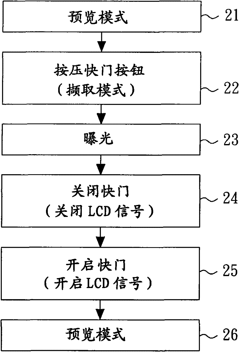
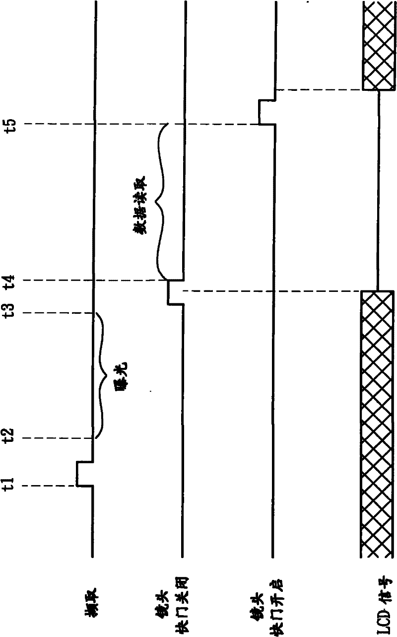
The invention relates to a camera and an operation method. The camera operation method comprises the following steps: a shutter button is pressed in order to trigger image capture; and a display relative signal is separated when image data is read from an image sensor so that the relative signal can not interfere with an image which is captured by the camera. The camera comprises a main circuit board, a display panel, a display flexible printed circuit, the image sensor and an image sensor flexible printed circuit, wherein a processor is arranged on the main circuit board; the display flexible printed circuit is coupled between the display panel and the main circuit board and is used for transmitting at least one display relative signal between the display panel and the main circuit board; the image sensor flexible printed circuit is coupled between the image sensor and the main circuit board and is used for transmitting at least one image signal between the image sensor and the main circuit board; and after the shutter button is pressed in order to trigger the image capture, the display relative signal is separated by the processor during at least one period in which the image data is read from the image sensor. The interference between the display panel and the image sensor is reduced through the technical scheme which is provided by the invention.

Description

technical field [0001] The present invention relates to a digital camera (digital camera), in particular to a technology for reducing the interference among electronic circuits in the digital camera. Background technique [0002] A digital camera contains many electronic circuits or systems, which will interfere with each other and produce adverse effects, thereby reducing the quality of the photos taken. Interference is usually caused by unwanted or unavoidable coupling between one circuit and another. For example, a liquid crystal display (LCD) clock signal transmitted on a flexible printed circuit (flexible printed circuit) (FPC) will be coupled to a charge-coupled device transmitted by another flexible printed circuit through a bracket supporting the LCD (CCD) image reads data, thus causing diagonal stripes in photographs. As digital cameras become smaller and thinner, the interference phenomenon will become more serious. Interference reduction can be achieved by usin...

Claims


Application Information

Patent Timeline
IPC IPC(8): H04N5/232H04N5/225
Inventor 蔡昆旭陈建复王志元
Owner ABILITY ENTERPRISE CO LTD
Learn More