Vehicle sunroof device

A technology for skylights and vehicles, which is applied to vehicle components, transportation and packaging, roofs, etc., can solve problems such as increased loads, and achieve the effect of reducing loads and avoiding large-scale

Active Publication Date: 2012-02-08
AISIN SEIKI KK
View PDF12 Cites 11 Cited by
  • Summary
  • Abstract
  • Description
  • Claims
  • Application Information

AI Technical Summary

Problems solved by technology

Assuming that when the tilt-up operation stroke is reduced, the load per unit operation stroke increases, and accordi

Method used


Image

  • Vehicle sunroof device
  • Vehicle sunroof device
  • Vehicle sunroof device

Examples


Example Embodiment

[0030] Hereinafter, an embodiment embodying the present invention will be described based on the drawings.

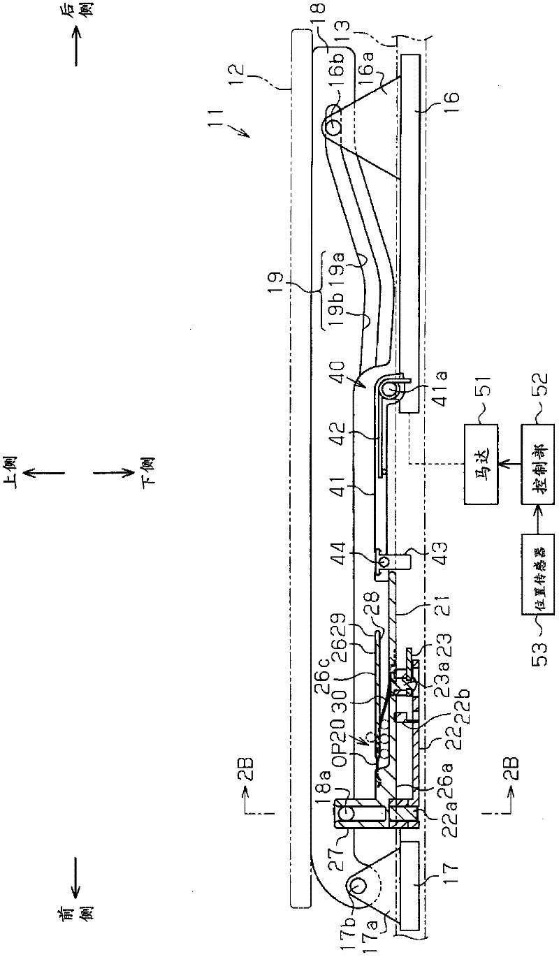
[0031] Figure 7 It is a schematic diagram when the sunroof device 11 mounted on the roof 10 which is a roof part of a vehicle, such as an automobile, is viewed diagonally from above. As shown in the figure, a roof opening 10a is formed in the roof 10. Furthermore, a movable panel 12 that opens and closes the roof opening 10a is mounted on the roof opening 10a. In addition, the movable panel 12 is attached to the roof 10 so as to be capable of tilting upward and sliding in the front and rear directions of the vehicle. In the opening and closing operation of the movable plate 12, a so-called outer sliding method that performs a sliding operation in an upwardly inclined state is adopted.

[0032] Next, the structure related to the opening and closing operation of the movable plate 12 will be described. In addition, the sunroof device 11 is provided with a structure related...


PUM


Abstract

A vehicle sunroof device includes a movable panel, guide rails, rear slide members, an electrical drive source, and chuck mechanisms. When the rear slide members are moved toward the front of the vehicle along the guide rails when the movable panel is in a totally closed state, the movable panel is changed to a tilt-up state. Chuck release mechanisms provided to the rear slide members are changed to an engaged state when the rear slide members are further moved toward the front of the vehicle with the movable panel in the tilt-up state and without involving operation of the movable panel. In the engaged state, when the rear slide members are moved toward the rear of the vehicle afterward, the chuck release mechanisms move the entire chuck mechanisms while switching the chuck mechanisms to a movable state. In the engaged state of the chuck release mechanisms, when the rear slide members are further moved toward the front of the vehicle without involving operation of the movable panel, the chuck release mechanisms are switched to an engagement released state in which the chuck release mechanisms are released from the chuck mechanisms.

Description

technical field [0001] The present invention relates to a sunroof device for a vehicle. Background technique [0002] Conventionally, a so-called outer slide sunroof device (outer slide sunroof) described in Patent Document 1 has been known as a vehicle sunroof device. In this device, in the fully closed state, when the guide shoes (shoes) arranged at the front and rear of the vehicle are moved rearward, the end of the lifting link connected to the guide rail in a rotatable manner rises, and the movable plate turns upward. lean state. In addition, if the guide shoes are moved further rearward in the upwardly inclined state, the movable panel moves rearwardly in the upwardly inclined state, and transitions to the fully opened state. [0003] Patent Document 1: Japanese Patent Laid-Open No. 2005-153803 [0004] However, in the vehicle sunroof device of Patent Document 1, since the moving amount (movement stroke) of the above-mentioned guide shoe required for the movable pan...

Claims


Application Information

Patent Timeline
IPC IPC(8): B60J7/05B60J7/02
CPCB60J7/024B60J7/0435B60J7/043
Inventor 沢田和希
Owner AISIN SEIKI KK
Why Eureka
Try Eureka