Feed pre-positioning method and device for molded plate

A front positioning and sheet material technology, applied in feeding devices, wood processing equipment, sawing components, etc., can solve the problems of complex drive structure, low production efficiency, inconvenient debugging, etc., and achieve high positioning and conveying effects and a high degree of automation High, compact process effect

Inactive Publication Date: 2012-02-15
CHANGZHOU HUAWANG MECHANIC MFG CO LTD
View PDF7 Cites 30 Cited by
  • Summary
  • Abstract
  • Description
  • Claims
  • Application Information

AI Technical Summary

Problems solved by technology

Manually place the sheet on the conveying table, manually position the sheet and push it into the multi-blade saw for cutting, not only the production efficiency is low, but also the finished product is low
2. Use semi-automatic positioning and cutting. If you use a positioning ruler to position the sheet and enter it into a multi-blade saw for cutting, these positioning methods must be manually involved in the positioning, and it is impossible to complete the fully automatic cutting production of the molded floor.
It has the advantages of high production efficiency and improved yield of cutting sheets. The positioning device uses more than two groove positioning rods to locate the groove in the middle of the sheet, because the groove positioning rod is positioned along the longitudinal direction of the sheet. , can effectively control the longitudinal offset phenomenon of the sheet metal, and also reduce the cumulative error caused by the manufacturing error of the sheet metal, but the bottom of the groove bar positioning rod is hemispherical or arc surface or V-shaped, during the downward movement of the sliding seat The position of the sheet is adjusted by contacting the bottom surface of the trough positioning rod with the sheet material, but since the trough positioning rod only moves downward, and the depth of the V-shaped groove of the sheet material is limited, the groove positioning rod is not easy to move. Large and heavy sheets reduce the reliability of automatic positioning
[0003] Furthermore, one kind of pressing mechanism is through pressing from top to bottom. It is to install a plurality of pressing cylinders on the frame, and press the material plate on the worktable through a plurality of pressing cylinders. Due to structural limitations, it will cause The deformation of the workbench where the sheet is placed affects the yield of the sheet
Another structure adopts the suction cup clamping structure, which can fix the sheet on the suction cup under the action of negative pressure gas, especially for some slightly warped sheets, the sheet can be flattened by negative pressure gas, so it can improve the cutting efficiency. The finished product rate of the slicing board is high, but there is also the problem of high cleanliness of the suction cup. Although the dust can be sucked into the air duct by the suction fan when cutting the material board, it will still affect the working environment and it is difficult to maintain the suction cup. Cleanliness due to reduced clamping force on the sheet
However, the driving mechanisms of the above two structures use the driving mechanism to push the workbench. On the one hand, the driving structure is complex and inconvenient to debug. On the other hand, because it drives the mobile workbench, the energy consumption is high.

Method used


Image

  • Feed pre-positioning method and device for molded plate
  • Feed pre-positioning method and device for molded plate
  • Feed pre-positioning method and device for molded plate

Examples


Embodiment Construction

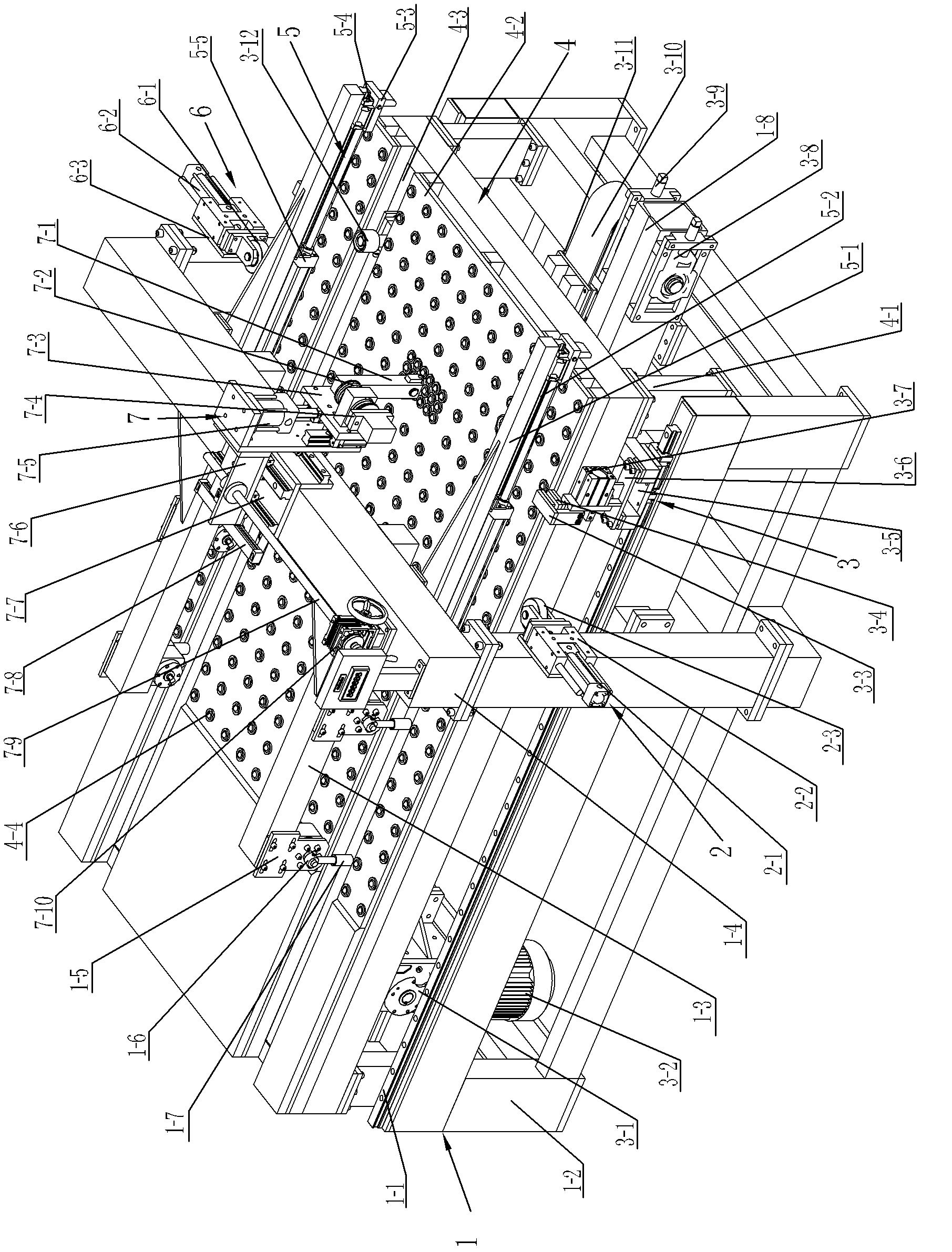
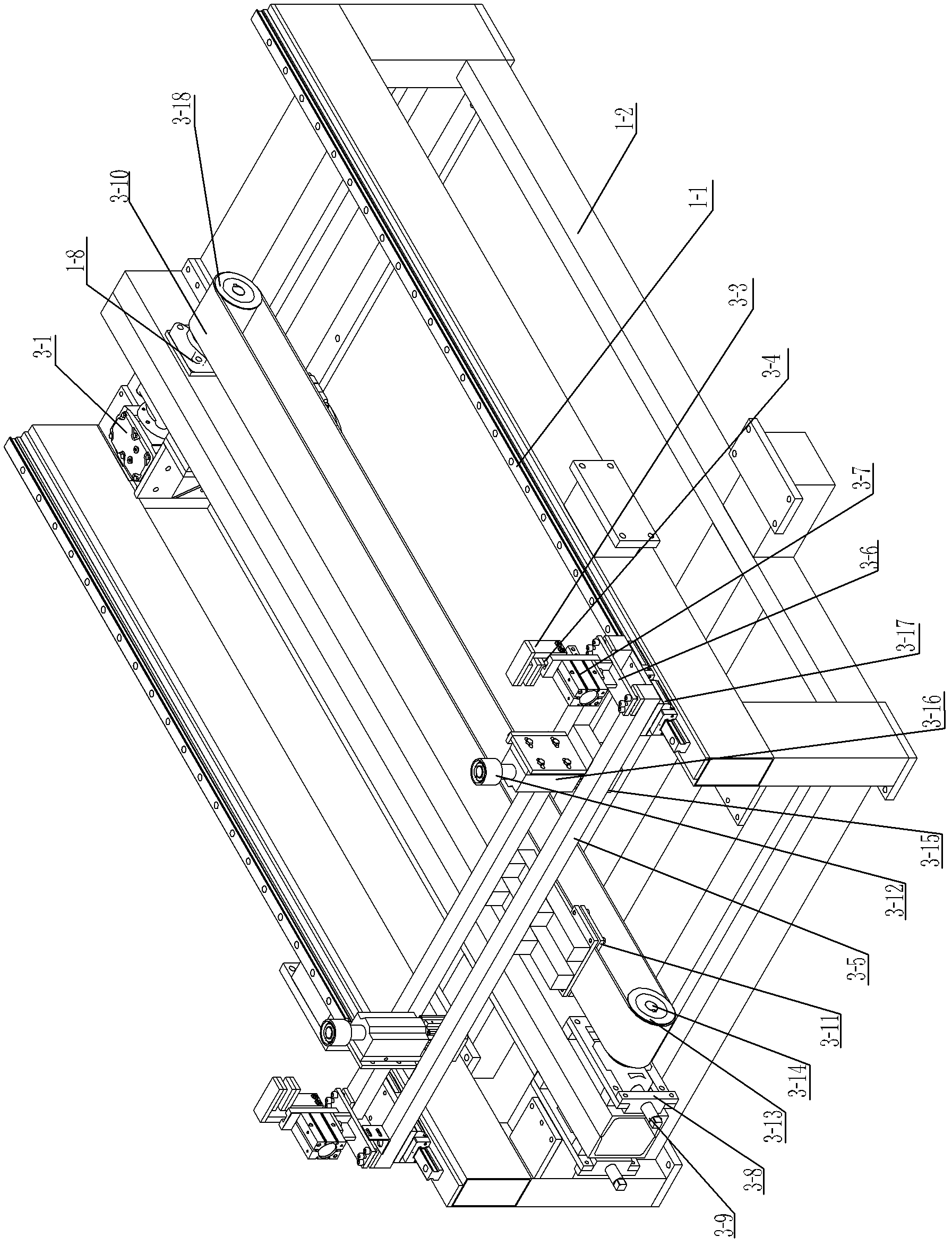
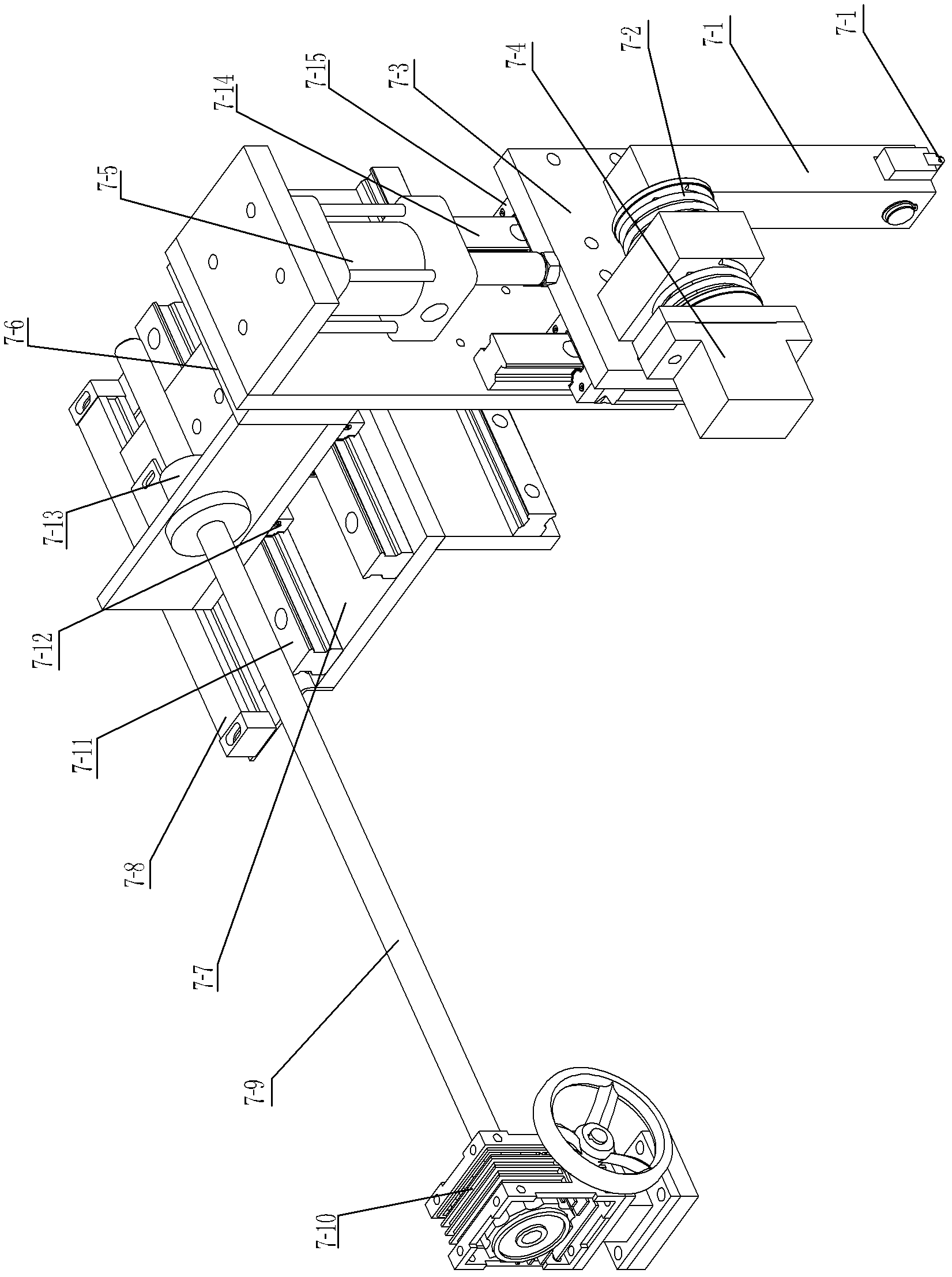
[0028] See Figure 1~3 As shown, the pre-feed positioning method of the molded plate of the present invention is to pull the plate with longitudinal grooves on the surface into the worktable 4-2 with the ball 4-4 through the pull plate 5-3, and by clamping Between the jaws of the cylinder 3-7, when the front surface of the sheet material contacts the two rotating arms 1-7, the rotating arm 1-7 sends out a signal, and the two positioning rings 3-12 stretch out and meet the rear end surface of the sheet material. connected, and under the action of the rotating arm 1-7, the rear end of the plate is connected to the two positioning rings 3-12 to realize the positioning of the rear end of the plate, and the side limiter 2-3 pushes the plate to make the plate The longitudinal groove on the material is located on the side of the positioning roller 7-16 at the bottom of the vibrating arm 7-1, the pull plate 5-3 and the side limiter 2-3 return to their original positions simultaneously...


PUM


Abstract

The invention relates to a feed pre-positioning device for a molded plate. The device comprises a frame mechanism, a working table, two pulling plate mechanisms, a lateral limiting mechanism, a lateral pushing mechanism, a vibration positioning mechanism and a supporting plate driving mechanism, wherein the frame mechanism comprises a supporting frame, a gantry frame and two upper longitudinal beams; the supporting frame has a framework structure; longitudinal driving guide rails are fixedly arranged on two sides of the top of the supporting frame respectively; the gantry frame is arranged across the supporting frame; the working table is fixedly arranged on the supporting frame; the two upper longitudinal beams are connected with the gantry frame; each upper longitudinal beam is longitudinally provided with at least two rotary cylinders in the backward and forward direction; the rotary cylinders are provided with rotary arms; a cross beam of the gantry frame is provided with at leasttwo pulling plate mechanisms and the vibration positioning mechanism; and the lateral limiting mechanism and the lateral pushing mechanism are arranged on two side beams of the gantry frame respectively. The device has the characteristics of rational structure, accurate positioning in a slot sheet, capability of increasing cutting yield, high universality and capability of clamping the sheet and driving the sheet to advance.

Description

technical field [0001] The invention relates to a pre-feeding positioning method and a device for a molded plate, belonging to the technical field of pre-cutting positioning of plates. Background technique [0002] The multi-blade saw is mainly composed of a frame, a transmission mechanism, a cutter shaft, multiple sets of circular saw blades installed on the cutter shaft, and a feeding mechanism. The composite floor or solid wood floor and other boards are placed on the feeding mechanism, and the positioning is carried out by the feeding mechanism. The sheet is sent to the saw blade at a constant speed for cutting into required sheet-shaped finished products, which can greatly improve production efficiency. The conventional plate feeding device is mainly composed of a positioning mechanism, a pressing mechanism and a pushing mechanism installed on the bracket. The positioning mechanism determines whether the plate is in place. The material is pushed into the slicing mechan...

Claims


Application Information

Patent Timeline
Patent Type & Authority Applications(China)
IPC IPC(8): B27B31/00
Inventor 王国强
Owner CHANGZHOU HUAWANG MECHANIC MFG CO LTD
Why Eureka
Try Eureka