Polar plate of micro-disc type focused logging device

A logging tool and electrode technology, which is used in surveying, wellbore/well components, earth-moving drilling, etc. Reasonable and other issues, to achieve the effect of improving work stability and measurement accuracy, wide measurement dynamic range, and large measurement dynamic range

Active Publication Date: 2012-02-15
西安威盛电子科技股份有限公司
View PDF7 Cites 5 Cited by
  • Summary
  • Abstract
  • Description
  • Claims
  • Application Information

AI Technical Summary

Problems solved by technology

Among them, the most important problem is: the plate size design is unreasonable, and the measurement main current phase changes greatly with the formation resistivity.
[0006] 2. The plate width is too large to be used in slim hole oil wells
In this way, although the width of the plate is reduced to 9cm, the detection depth of the small plate is also reduced by 40%. Since the method of microsphere focused logging requires a detection depth of 10-15cm, the newly developed microsphere focused small Due to the insufficient detection depth of the polar plate, it has not been widely used
[0009] 3. The old plate is not easy to combine with other logging tools
Practice has proved that reducing the width of the plate proportionally will greatly reduce the measurement performance of the instrument
Although the microcolumn focusing logging tool (MZFL) invented by Schlumberger Logging Company in the United States has narrowed the size of the plate, it has not been widely used because of the low resistivity (Rmc) of the mud cake.

Method used


Image

  • Polar plate of micro-disc type focused logging device
  • Polar plate of micro-disc type focused logging device
  • Polar plate of micro-disc type focused logging device

Examples


Embodiment Construction

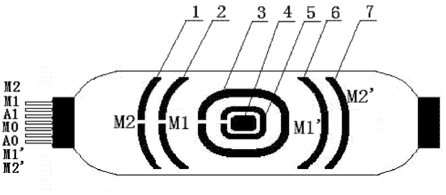
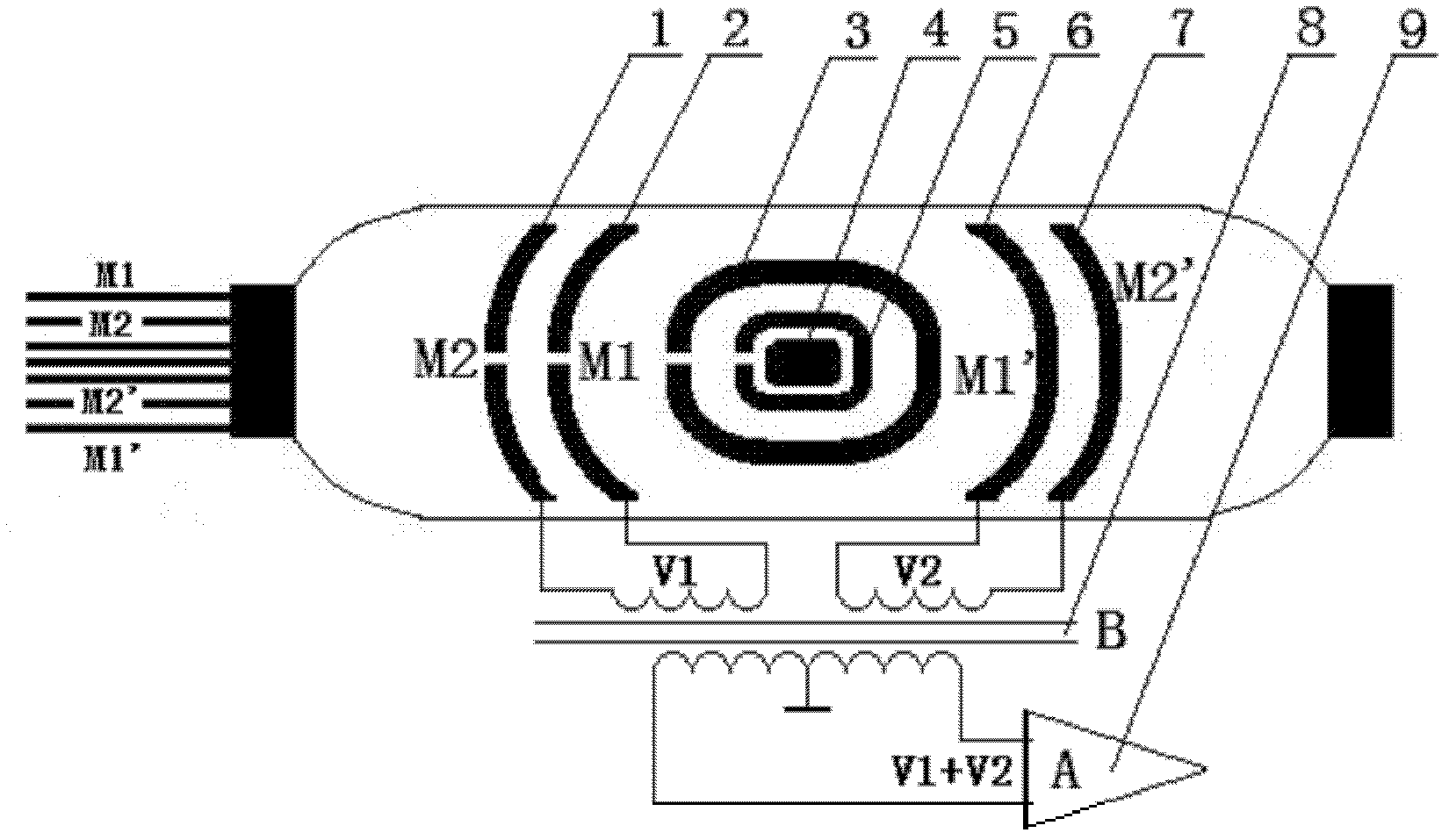
[0040] Such as figure 1 As shown, the plate of the microdisk type focused logging tool includes a plate with a rectangular structure with two ends and a plate electrode arranged on the surface of the plate, wherein: the plate electrode is included in the plate The main electrode A0 4 in the center of the board, and the ring electrode M0 5 and ring electrode A1 3 distributed from the inside to the outside of the main electrode A0 4 in turn; two groups of semicircular electrodes are symmetrically distributed on both sides of the ring electrode A1 3: Supervision Electrode M1 2 and monitoring electrode M1'6, monitoring electrode M2 ​​1 and monitoring electrode M2'7, and monitoring electrode M1 2, monitoring electrode M2'7, monitoring electrode M2 ​​1, monitoring electrode M1'6 to main electrode A0 4 electrode distance Equal, the two groups of monitoring electrodes synthesize the signals collected by the transformer and then control the main current measurement.

[0041] The pole ...


PUM


Abstract

The invention discloses a polar plate of a micro-disc type focused logging device. The polar plate comprises the polar plate and polar plate electrodes arranged on the plate surface of the polar plate, wherein the polar plate is in the shape of a rectangle, the two ends of the polar plate are in circular arc-shaped structures, and the polar plate electrodes comprise a main electrode A0 at the center of the plate surface of the polar plate, as well as an annular electrode M0 and an annular electrode A1 which are sequentially distributed on the periphery of the main electrode A0 from inside to outside; and two groups of semi-circular electrodes, namely a monitor electrode M1 and a monitor electrode M1', as well as monitor electrode M2 and a monitor electrode M2', are symmetrically distributed on the two sides of the annular electrode A1, the electrode distances from the monitor electrode M1, the monitor electrode M2', the monitor electrode M2 and the monitor electrode M1' to the main electrode A0 are equal, and after signals acquired by the two groups of the monitor electrodes are synthesized by a transformer, the two groups of the monitor electrodes controls the main current measurement. Since the electrodes of the novel polar plate are the two groups of the semi-circular type electrode structures and the overall dimension and the shape of the polar plate are further changed, the novel polar plate has the advantages of stable electric field, a large measurement dynamic range, high measurement precision, good layering capability and the like.

Description

technical field [0001] The invention relates to a novel micro-focus series logging instrument polar plate, in particular to a sensor-micro-disk focusing polar plate (MPFL) of a novel micro-disk focused logging tool. Background technique [0002] In the field of petroleum geological logging, it is currently the most effective logging interpretation method to judge the properties of oil, gas, and water in the formation by measuring the change of resistivity at different depths in the lateral direction (perpendicular to the well axis). The microsphere focusing series logging tool is the best method to measure the resistivity Rxo of the formation flushing zone at home and abroad. [0003] The original Microsphere Focused Logging tool plate was designed in 1983 with reference to the Microsphere Focused Logging (MSFL) tool of Schlumberger Company. After more than 20 years of use, the plate has the following problems: [0004] 1. The measurement curve of the plate electric field ...

Claims


Application Information

Patent Timeline
Patent Type & Authority Applications(China)
IPC IPC(8): E21B47/00E21B49/00
Inventor 詹保平张国辉滑宝成
Owner 西安威盛电子科技股份有限公司
Why Eureka
Try Eureka