
Tunnel kiln

A tunnel kiln and furnace technology, which is applied to furnaces, furnace types, lighting and heating equipment, etc., can solve the problem of short-circuiting in the installation structure of resistance wires, and achieve the effect of simple structure, easy implementation and short-circuit avoidance.

Inactive Publication Date: 2012-02-15
NINGGUO ZHICHENG MACHINERY MFG
View PDF6 Cites 5 Cited by
  • Summary
  • Abstract
  • Description
  • Claims
  • Application Information

AI Technical Summary

Problems solved by technology

[0003] The object of the present invention is to address the above problems and provide a tunnel kiln to solve the problem that the traditional resistance wire installation structure is prone to short circuit

Method used


Image

  • Tunnel kiln
  • Tunnel kiln
  • Tunnel kiln

Examples


Embodiment Construction

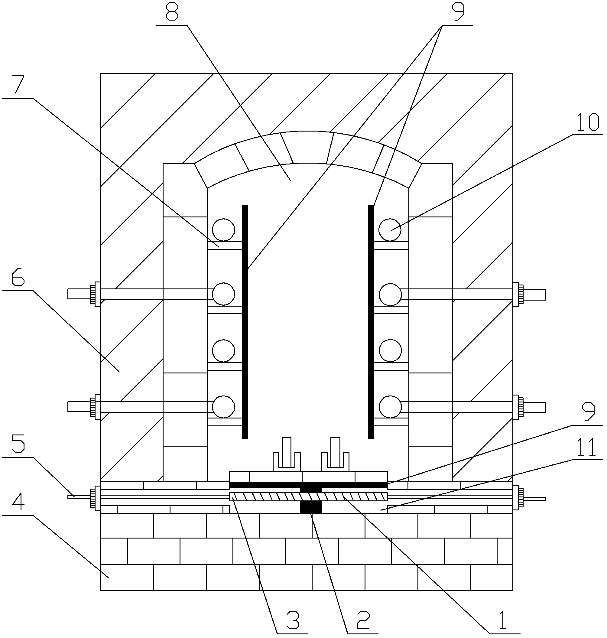
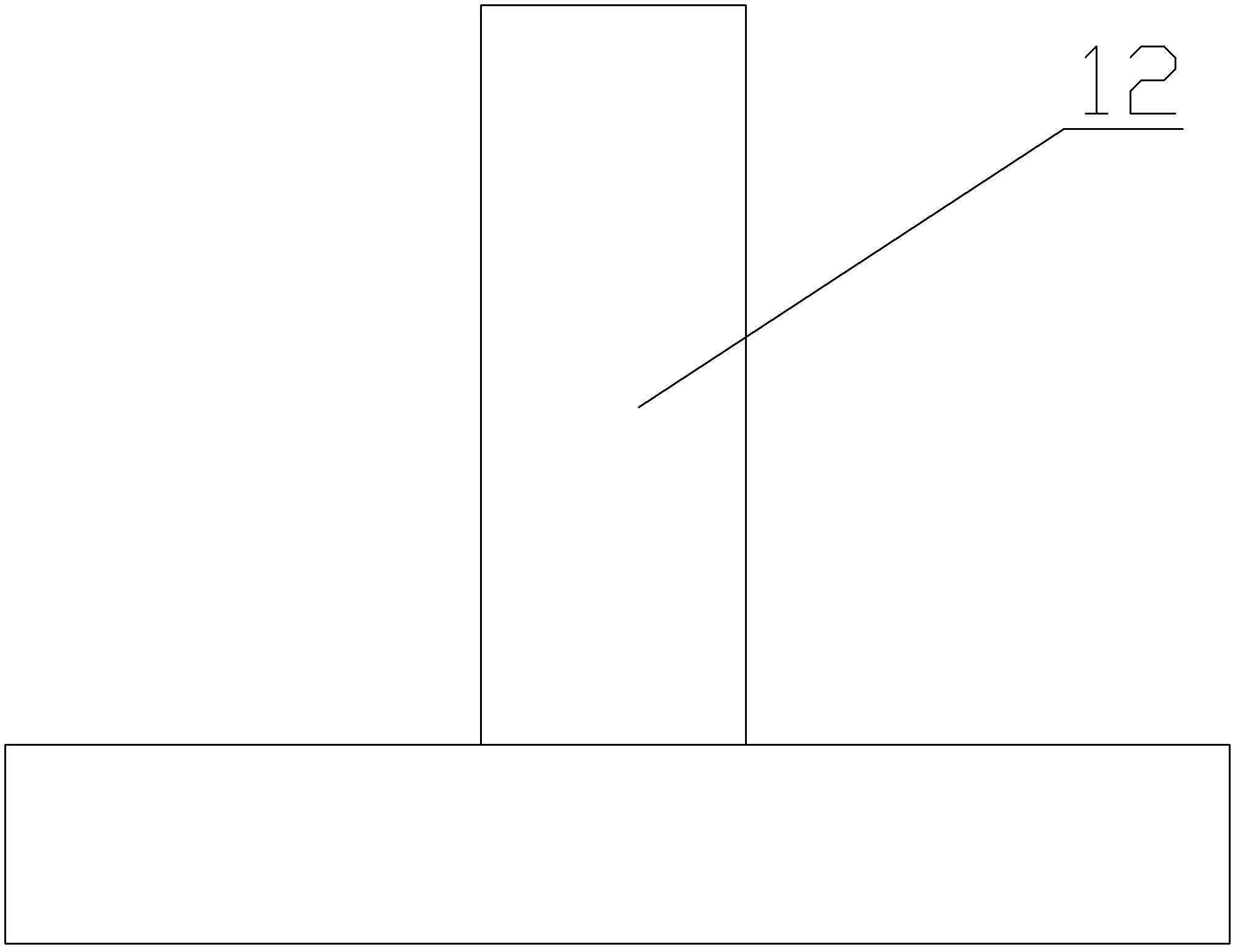
[0015] Please refer to figure 1 and figure 2 as shown, figure 1 It is the structural representation of the tunnel kiln of the present invention; figure 2 It is a structural schematic diagram of an inverted T-shaped wire shelf brick of the present invention.

[0016] In this embodiment, a tunnel kiln includes a hearth 8, a furnace bottom 4 and a furnace body 6, on both sides of the hearth 8 there are shelving bricks 7, and on said shelving bricks 7 are placed resistance wires 10 One end of the silk brick 7 is connected to the furnace body 6, and the other end is equipped with a protective cover plate 9. The furnace bottom 4 is provided with a groove 11, and the groove 11 is located below the furnace 8 and is provided with vertically arranged inverted T-shaped wire laying brick 2, a font-shaped resistance wire 1 is arranged horizontally on both sides of the inverted T-shaped wire laying brick 2, and a protective cover plate 9 is installed above the convex column 12 of the i...


PUM


Abstract

The invention discloses a tunnel kiln which comprises a hearth, a furnace bottom and a furnace body, wherein two sides of the hearth are provided with resistance wire holding bricks, resistance wires are arranged on the resistance wire holding bricks, one end of each resistance wire holding brick is connected with the furnace body and the other end is provided with a protective cover plate, the furnace bottom is provided with a groove, inverted T-shaped resistance wire holding bricks are longitudinally arranged at the part of the groove below the hearth, two sides of the reversed T-shaped resistance wire holding bricks are horizontally provided with linear resistance wires, and protective cover plates are installed on protruding columns of the reversed T-shaped resistance wire holding bricks. According to the invention, the protective cover plates are added to the tunnel kiln so as to avoid the contact between metal workpieces and the resistance wires on the resistance wire holding bricks and further avoid short circuit; meanwhile, heat dissipation holes arranged on the protective cover plates can speed up the circulation of high-temperature heat in the furnace, thereby effectively prolonging the service life of the resistance wires. The tunnel kiln has a simple structure and is easy to realize.

Description

technical field [0001] The invention relates to a tunnel kiln. Background technique [0002] At present, in the heat treatment production of large-scale wear-resistant castings, tunnel kilns are mostly used as furnaces. In terms of the structure of the furnace chamber, the traditional tunnel furnace is to set the resistance wire in a U-shape and place it on the special wire brick for the furnace. However, this setting is likely to cause a short circuit in the contact between the resistance wire and the heated metal workpiece, which will lead to the interruption of the normal production of the heat treatment of wear-resistant castings. Contents of the invention [0003] The object of the present invention is to address the above problems and provide a tunnel kiln to solve the problem that the traditional resistance wire installation structure is prone to short circuit. [0004] The purpose of the present invention is to realize through the following technical solutions: ...

Claims


Application Information

Patent Timeline
IPC IPC(8): F27B9/06F27B9/30F27B9/36
Inventor 姜庆志梅玉宝
Owner NINGGUO ZHICHENG MACHINERY MFG
Learn More