Homotaxial magnetic turning column liquid level meter

A magnetic flipping column and liquid level gauge technology, applied in the field of liquid level gauges, can solve the problems of magnetic float 2 stuck, damaged, and difficult to handle, and achieve the effect of not easy to get stuck and damaged, no valve leakage, and expanded measuring range

Inactive Publication Date: 2012-11-14
苏州苏控自动化设备有限公司 +1
View PDF6 Cites 0 Cited by
  • Summary
  • Abstract
  • Description
  • Claims
  • Application Information

AI Technical Summary

Problems solved by technology

The disadvantages are: 1) holes must be made on the side of the container, which is inconvenient for processing and installation; 2) the liquid level gauge needs to be in contact with the liquid inside the container through the valve 13, which will easily cause the magnetic float 2 to get stuck and damaged after a long time. If the valve leaks or is damaged, it will be very difficult to deal with; 3) The length of the liquid level gauge is related to the height (range) of the liquid in the container, that is, a 20-meter container must use a 20-meter magnetic turning column 1, so that the liquid used for a large range The installation, transportation and disassembly of the position meter are very inconvenient
But its existing defects are: 1) Same as the above-mentioned side-mounted magnetic flip column liquid level gauge, the length of the liquid level gauge is related to the height of the liquid in the container 100, and the installation, transportation and disassembly of the liquid level gauge are inconvenient; 2) The scale of the liquid level gauge is a negative scale (that is, the 0m position of the liquid level gauge is at the top of the liquid level gauge, and the full scale is at the bottom of the liquid level gauge), so the on-site display and the actual liquid level are in an inverted state, and it is very inconvenient to observe the liquid level gauge
However, its disadvantages are: 1) The length of the liquid level gauge should be adapted to the depth of the liquid in the pool. Once the depth of the pool exceeds 3 meters, it will be extremely inconvenient to install and maintain the liquid level gauge; 2) The liquid level gauge must be installed in the Directly above the measured point; if the directly above the measured point cannot meet the installation requirements of the liquid level gauge (such as an open pool, etc.), it will not be used

Method used


Image

  • Homotaxial magnetic turning column liquid level meter
  • Homotaxial magnetic turning column liquid level meter
  • Homotaxial magnetic turning column liquid level meter

Examples


Embodiment 1

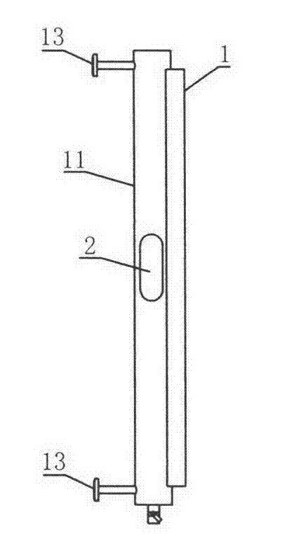
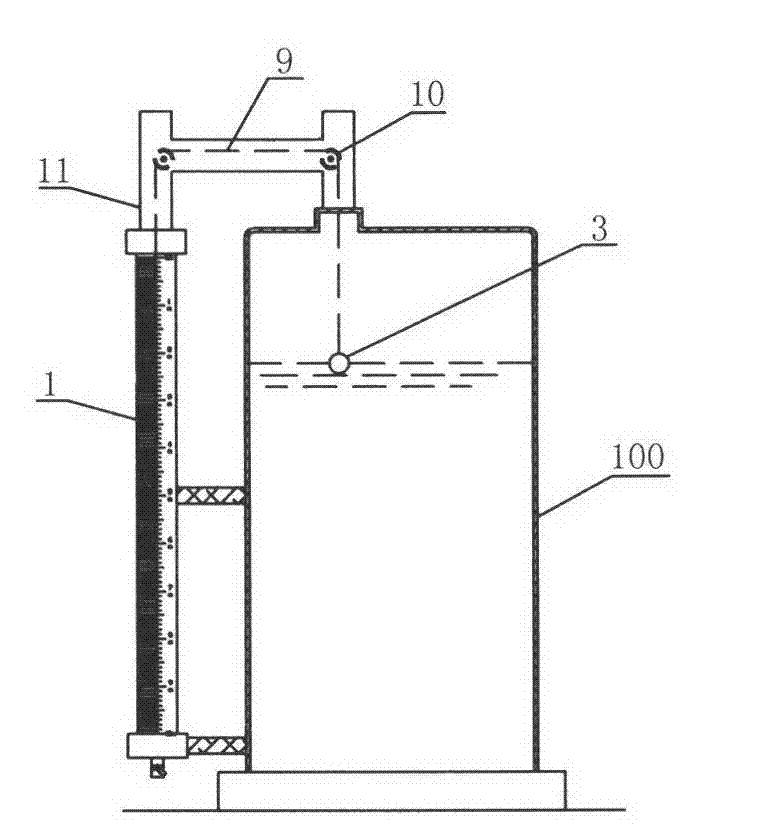
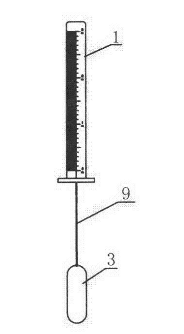
[0027] The uniaxial magnetic column liquid level gauge of this embodiment is as follows: Figure 4 and Figure 5 As shown, it includes a magnetic turning column 1, a magnetic float 2 parallel to the magnetic turning column 1 and a floating body 3 arranged on the surface of the liquid to be tested. It also includes a transmission mechanism 4 and a hammer body 5. The transmission mechanism 4 is mainly composed of a single rotating shaft 7 arranged in the housing 6 and two runners 8-1 and 8-2 sleeved on the rotating shaft 7. The floating body 3 passes The rope 9 and the pulley 10 are wound around the first runner 8-1, and the magnetic float 2 and the hammer body 5 are wound around the both sides of the second runner 8-2 by the rope 9, as Image 6 shown.

[0028] like Figure 5 As shown, the single-axis magnetic flip column liquid level gauge of this embodiment also includes a magnetic float cavity 11 and a hammer body cavity 12 that are parallel to the magnetic flip column 1. ...

Embodiment 2

[0050] The uniaxial magnetic column liquid level gauge of this embodiment is as follows: Figure 7 Shown, is the improvement on the basis of embodiment one, and its structure is basically the same as embodiment one, and difference is: 1) the running wheel that is sleeved on the rotating shaft 7 is three (promptly two in embodiment one Add a runner on the runner basis), respectively the first runner 8-1, the second runner 8-2 and the third runner 8-3; 2) the magnetic float 2 is wound around the second runner by the rope 9 Then 8-2 is wound around, and hammer body 5 is wound around with third runner 8-3 by rope 9.

[0051] Generally, the rope 9 connecting the magnetic float 2, the floating body 3 and the hammer body 5 will be pre-wound a certain number of turns (more than one turn) on the runners 8-2, 8-1, 8-3 respectively.

Embodiment 3

[0053] The uniaxial magnetic column liquid level gauge of this embodiment is as follows: Figure 8 What is shown is a change based on the second embodiment, and its structure is basically the same as that of the second embodiment, except that the transmission mechanism 4 is fixed on the container 100 containing the liquid to be tested.


PUM


Abstract

The invention relates to a homotaxial magnetic turning column liquid level meter, which belongs to the technical field of liquid level meters. The liquid level meter comprises a magnetic turning column, a magnetic float which is abutted with the magnetic turning column in parallel and a floating body which is arranged at the surface of the liquid to be measured, and further comprises a transmission mechanism and a hammer body which are fixedly arranged on the magnetic turning column, wherein the transmission mechanism is formed by a single rotating shaft which is arranged in a shell and two or three turning wheels which are sleeved on the rotating shaft, the floating body is connected with a first turning wheel through a rope and a pulley in a wrapping way, and the magnetic float and the hammer body are connected with the two sides of a second turning wheel through a rope in the wrapping way; or the magnetic float is connected with the second turning wheel through a rope in the wrapping way, and the hammer body is connected with a third turning wheel through a rope in the wrapping way; and when the rotating shaft rotates, the movement directions of the floating body and the magnetic float are same and are opposite to that of the hammer body. Through selecting the turning wheels with different diameters, the liquid level measurement range can be widened, so the liquid level meter can be more conveniently installed, transported and dismantled; and in addition, clamping stagnation or damage is not easy to cause, no valve leakage is generated, and the observation is very convenient.

Description

technical field [0001] The invention relates to a magnetic flip column liquid level gauge, which belongs to the technical field of liquid level gauges. Background technique [0002] Magnetic column level gauge (also known as magnetic float level gauge) is developed based on the principle of buoyancy and magnetic coupling. It makes up for the multiple shortcomings of traditional glass tube level gauges that cannot work under high temperature and high pressure and are fragile. When the liquid level in the measured container rises and falls, the magnetic float in the cavity of the magnetic column liquid level gauge also rises and falls, and the permanent magnet steel in the float is transmitted to the magnetic column indicator through magnetic coupling to drive the red and white indicators. The column turns 180°, when the liquid level rises, the turning column turns from white to red, when the liquid level drops, the turning column turns from red to white, and the red and white...

Claims


Application Information

Patent Timeline
Patent Type & Authority Patents(China)
IPC IPC(8): G01F23/46
Inventor 冯贤生冯继明
Owner 苏州苏控自动化设备有限公司
Why Eureka
Try Eureka