Mutual inductor automation detecting system

A fully automated, transformer technology, used in instruments, measuring devices, measuring electrical variables, etc., can solve the problems of not meeting the requirements of transformer verification, and not reflecting the advantages of automated assembly line operations, to improve stability and accuracy, Easy to manage and efficient

Active Publication Date: 2014-03-19
STATE GRID ZHEJIANG ELECTRIC POWER +1
View PDF5 Cites 0 Cited by
  • Summary
  • Abstract
  • Description
  • Claims
  • Application Information

AI Technical Summary

Problems solved by technology

The crimping methods of the primary windings of the two types of transformers are different, and the busbar type transformers with different transformation ratios have different appearance dimensions, central apertures and positions. Therefore, the transformer verification system needs to adapt to the different wiring of busbar type and double-turn current transformers. method and different size requirements; a single set of transformer automatic verification devices cannot meet the verification requirements of a large number of transformers, and at the same time cannot reflect the advantages of automated assembly line operations, so the transformer verification system needs to consider the organic combination of multiple sets of transformer verification devices

Method used


Image

  • Mutual inductor automation detecting system
  • Mutual inductor automation detecting system

Examples


Embodiment Construction

[0030] The technical solution of the present invention will be further described in detail below in conjunction with the accompanying drawings.

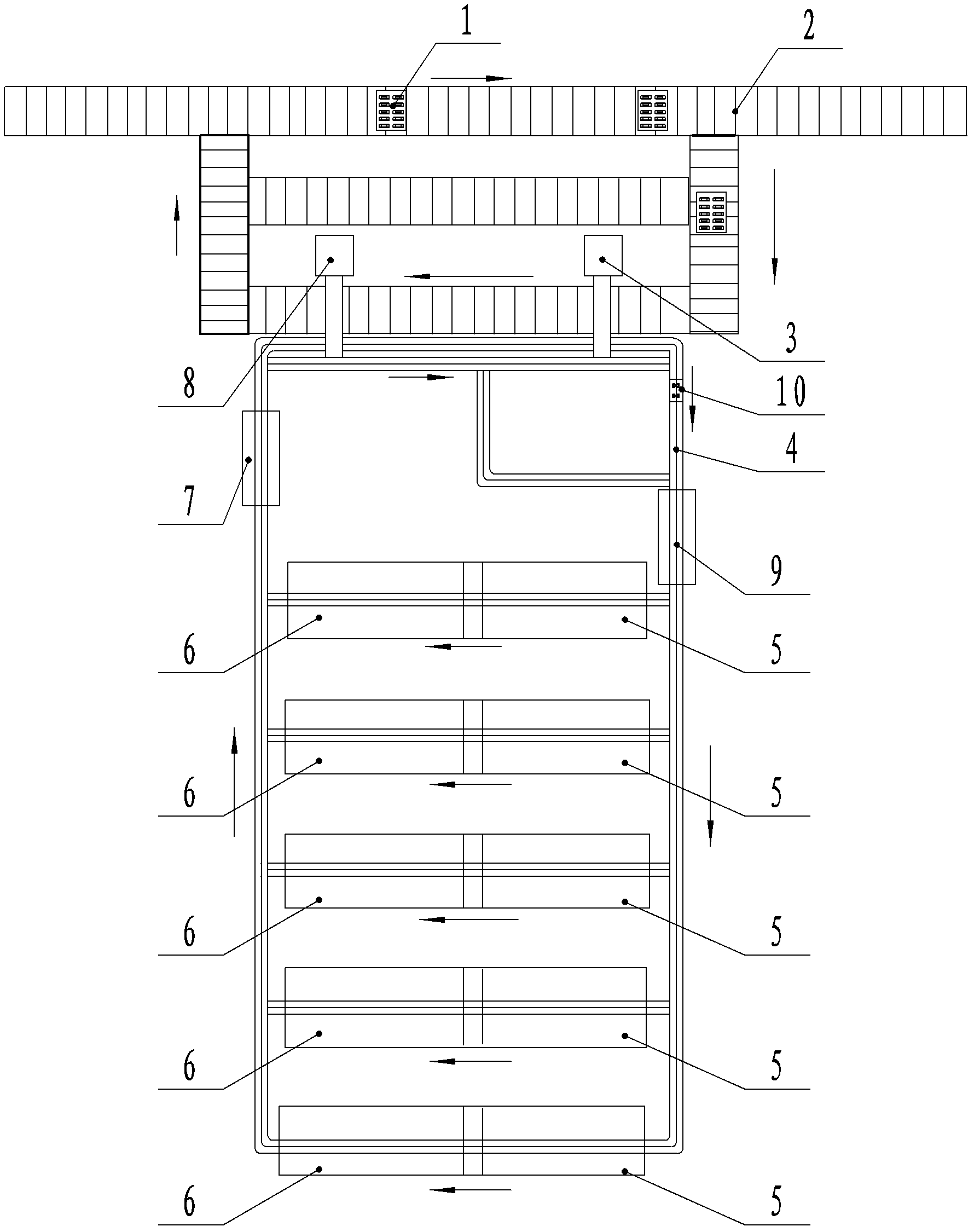
[0031] The present invention is used for transporting the turnover box 1 to transport the turnover box 1 equipped with the transformer to be inspected from the storage system to the loading station and transport the turnover box 1 equipped with the inspected transformer located at the unloading station back to the storage system The feeding conveying line 2 of the feeding conveying line; the feeding device 3 located next to the feeding station of the feeding conveying line 2 for moving the transformer located at the feeding station of the feeding conveying line 2 to the verification conveying line 4; The transformer is moved to the verification transmission line 4 of the corresponding station of each device; the appearance inspection device 9 is used to take pictures of the appearance of the transformer and handle it; the inspection d...


PUM


Abstract

A mutual inductor automation detecting system, which relates to a current transformer detecting system, is disclosed. At present, in a traditional mutual inductor detecting device, a semi-automatic working mode is adopted, and wiring and disconnecting works are completed by manual work so that working efficiency is low, labor intensity is large and artificial wiring can intervene a detecting result. The traditional mutual inductor detecting device has may other problems and can not satisfy a fast-growing mutual inductor detecting demand. The system is characterized in that: the system comprises: a material feeding transmission line, a material feeding device, a detecting transmission lime, a preventive testing device, an error detecting device, a laser marking apparatus, a blanking apparatus and a detecting management system; the preventive testing device, the error detecting device and the laser marking apparatus are successively arranged beside the detecting transmission lime. The material feeding transmission line, the detecting transmission lime and the each apparatus perform coordination work so that full automatic detection of the mutual inductor can be realized. Efficiency is high. Artificial detection faults can be avoided. Sorting accuracy can be raised. The laser marking substitutes a traditional mode of sticking certifications, which is beneficial to manage and use the mutual inductor.

Description

technical field [0001] The invention relates to a verification system of a current transformer. Background technique [0002] The current transformers currently used in the power grid reduce the large current in the primary line to the small current required by the secondary measurement circuit, and mainly realize the functions of electrical isolation and proportional measurement at both ends of the high and low voltage. Metering current transformer is one of the main measuring instruments used for trade settlement in the power grid, and belongs to the national compulsory verification specification. Each metering current transformer needs to pass the initial verification and periodic verification before it can be used normally. With the rapid development of the economy, the new increase and inventory of current transformers for measurement have risen sharply. The traditional manual verification method has problems such as low work efficiency, high labor intensity, and manua...

Claims


Application Information

Patent Timeline
Patent Type & Authority Patents(China)
IPC IPC(8): G01R35/02
Inventor 朱炯韩宵汉张燕黄金娟周永佳徐永进
Owner STATE GRID ZHEJIANG ELECTRIC POWER
Why Eureka
Try Eureka