Ka frequency-band solid-state power amplifier

A power amplifier, a solid-state power technology, is applied to the power amplification of satellite communication microwave channels. field, it can solve the problems of reducing synthesis efficiency, increasing equipment power consumption, reducing output power, etc., and achieves the effects of low loss, increased isolation, and convenient adjustment

Inactive Publication Date: 2012-02-15
NO 54 INST OF CHINA ELECTRONICS SCI & TECH GRP
View PDF3 Cites 19 Cited by
  • Summary
  • Abstract
  • Description
  • Claims
  • Application Information

AI Technical Summary

Benefits of technology

In this patented technical solution described by the inventor's current design, there are several benefits that make it better than previous designs such as lower losses, higher efficiency, greater flexibility in terms of modulation types, improved stability over longer periods of usage without being damaged easily, etc., resulting in more efficient energy utilization compared to existing solutions like traditional radio frequency transmitters.

Problems solved by technology

The technical problem addressed in this patented text relates to improving the performance of aluminum nitride (AlN) ceramic material used in electronic devices like radios or microwave filters due to their ability to transmit signals over longer distances without losing too much energy compared to traditional materials like silicon dioxide (SiO2). This improvement could be useful in developing smaller satellites and other applications where space constraints require efficient power amplifiers.

Method used


Image

  • Ka frequency-band solid-state power amplifier
  • Ka frequency-band solid-state power amplifier
  • Ka frequency-band solid-state power amplifier

Examples


Embodiment Construction

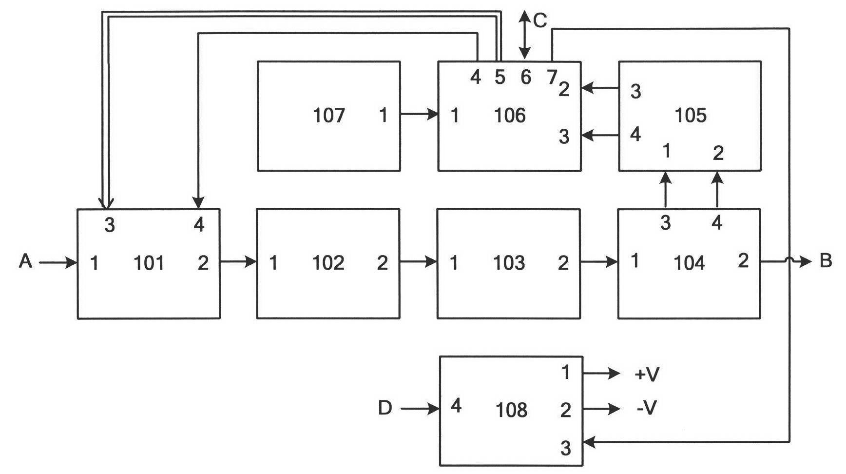
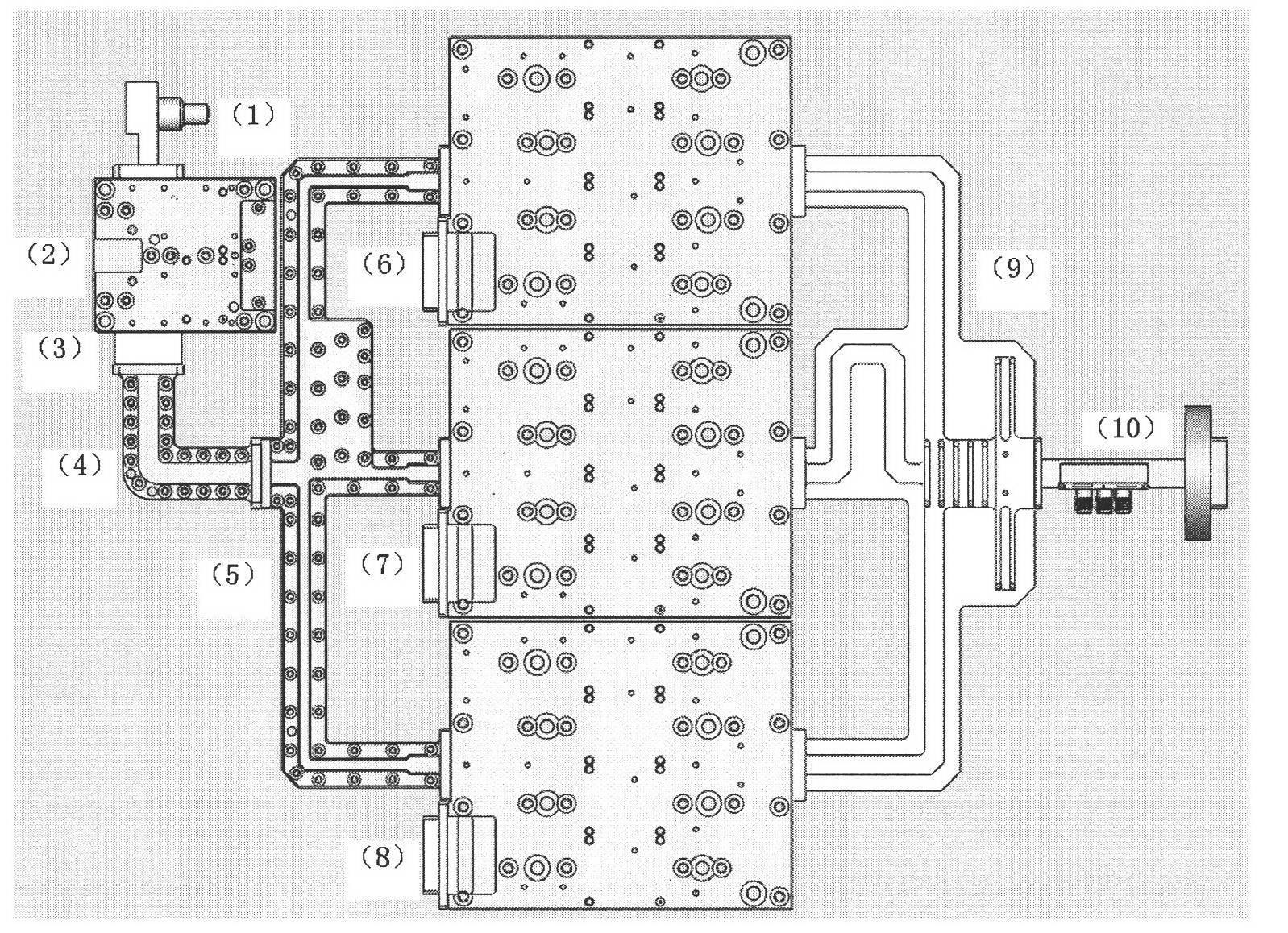
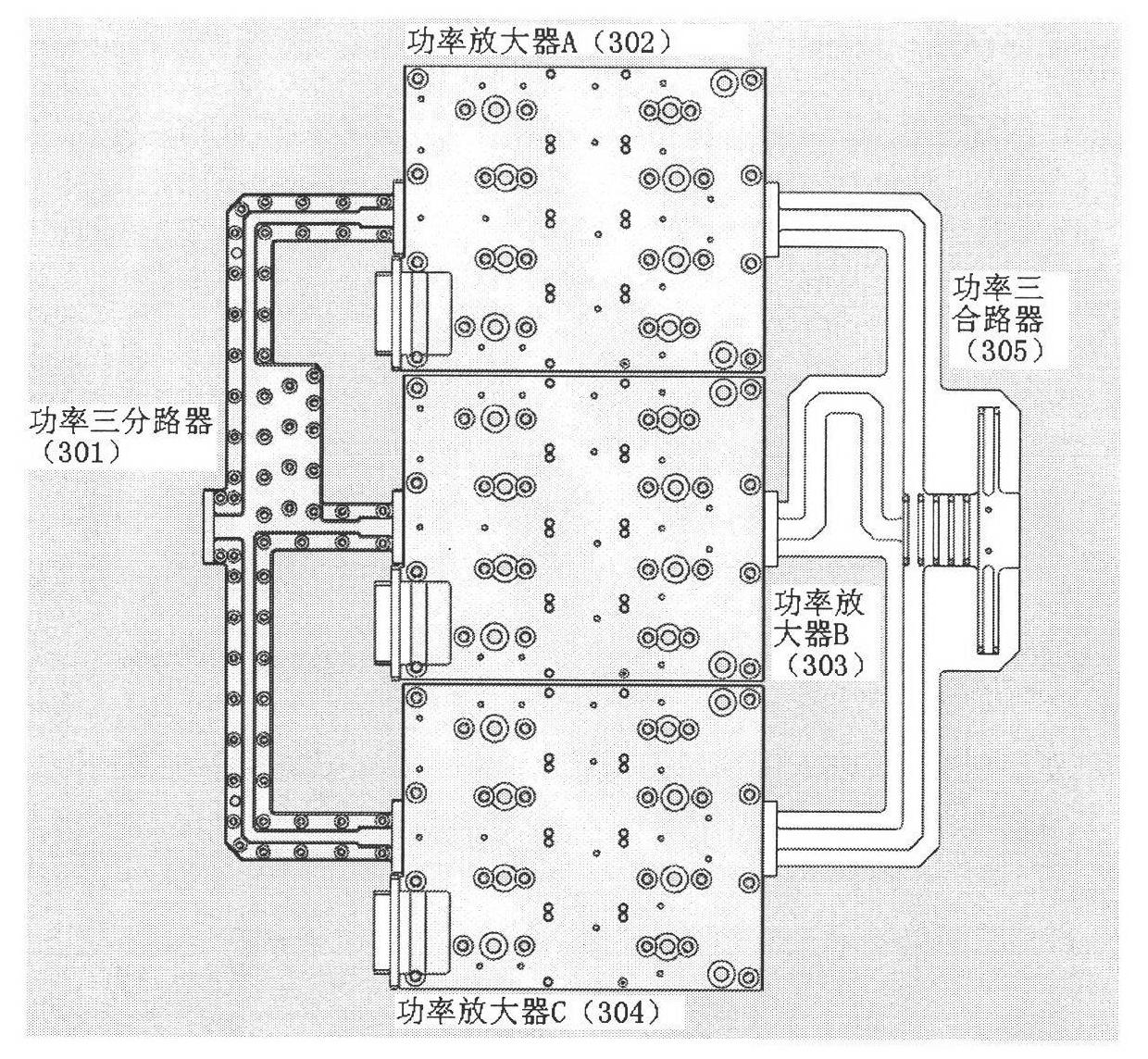
[0022] refer to Figure 1 to Figure 6 , the present invention is composed of a level control unit 101, a drive amplifier 102, a solid-state power amplifier module 103, an output coupler 104, a wave detector 105, a monitoring unit 106, a temperature sensor 107, and a module power supply 108. figure 1 It is a principle block diagram of the present invention, and the embodiment is according to figure 1Connecting lines, the level control unit 101 of the present invention enters 1 pin and connects with external port A through a low-loss coaxial cable to realize Ka frequency band signal input. The adjustment of the gain of the device itself is realized according to the system requirements, and the digitally controlled attenuator in the level control unit 101 is made of a commercially available TGATT2931-30 attenuator. The 4 pins of the input end are connected with the 4 pins of the output end of the monitoring unit 106. The first function is to realize the gain stability of the tra...


PUM


Abstract

The invention discloses a Ka frequency-band solid-state power amplifier, which relates to an uplink channel transmission device in the field of satellite communication. The solid-state power amplifier comprises a level control unit, a driving amplifier, a solid-state power amplification module, an output coupler, a wave detector, a monitoring unit, a temperature sensor, a module power supply, and the like. The invention relates to an intra-waveguide space 12-route power combining technique, and a three-route waveguide power splitter and a three-route power combiner for waveguide branch lines are designed; four power single-chips are assembled on a four-route power combiner consisting of the waveguide branch lines, waveguide T-shaped nodes, and waveguide-microstrip probes in a transitional manner; and three four-route power combining modules subjected to special testing, together with a three-route power splitter and a four-route power combiner, from a 12-route power combining module. The power amplifier disclosed by the invention has the characteristics of compact structure, high integration degree, stable and reliable performance, light weight, low power consumption, and wide operating temperature range; and the power amplifier is especially applicable to the power amplification services of satellite communication microwave channels.

Description


Claims


Application Information

Patent Timeline
Owner NO 54 INST OF CHINA ELECTRONICS SCI & TECH GRP
Why Eureka
Try Eureka