Electric control pneumatic gear shifting handle mechanism and speed change system as well as vehicle using such mechanism

A pneumatic shifting and shifting handle technology, applied in mechanical equipment, components with teeth, transmission control and other directions, can solve the problems of signal transmission easily disturbed, the overall structure is not compact enough, and the electronic control equipment is complex. Improve the safety and reliability of operation, humanized operation, and the effect of compact overall structure

Active Publication Date: 2012-02-22
RUILI GROUP RUIAN AUTO PARTS CO LTD
View PDF7 Cites 9 Cited by
  • Summary
  • Abstract
  • Description
  • Claims
  • Application Information

AI Technical Summary

Problems solved by technology

For example, the application number is 200620097228.8, and the Chinese utility model patent titled "Electro-Control Pneumatic-Mechanical Automatic Transmission Gear Selection and Shifting Mechanism Assembly" is still not compact enough.
For example, the application number is 2009100256375, and the invention patent named "Gearbox Shift Control Mechanism" adopts non-contact sensors, the signal transmission is easily disturbed, the reliability is not high, the electronic control equipment is complicated, and it is not easy to maintain

Method used


Image

  • Electric control pneumatic gear shifting handle mechanism and speed change system as well as vehicle using such mechanism
  • Electric control pneumatic gear shifting handle mechanism and speed change system as well as vehicle using such mechanism
  • Electric control pneumatic gear shifting handle mechanism and speed change system as well as vehicle using such mechanism

Examples


Embodiment Construction

[0035] The content of the present invention will be described below in conjunction with the accompanying drawings. The following description is only exemplary and explanatory, and should not have any limiting effect on the protection scope of the present invention.

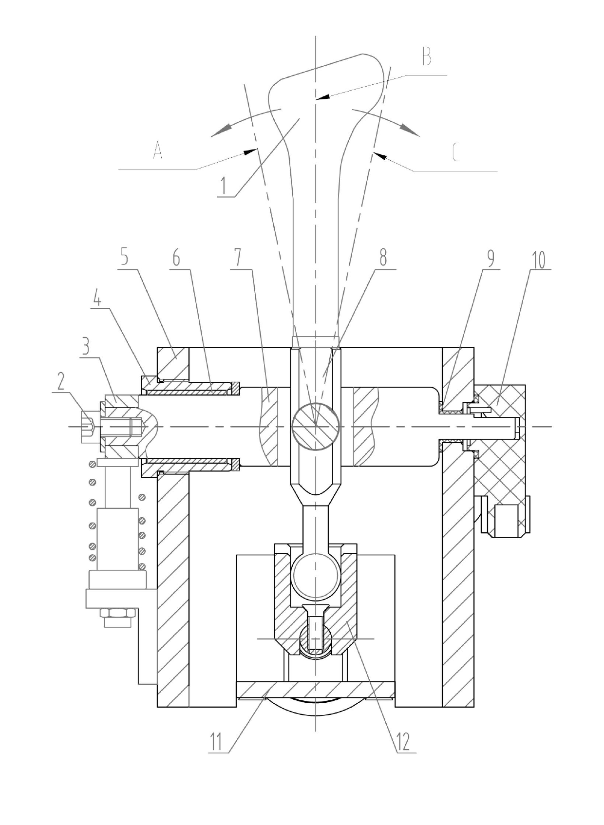
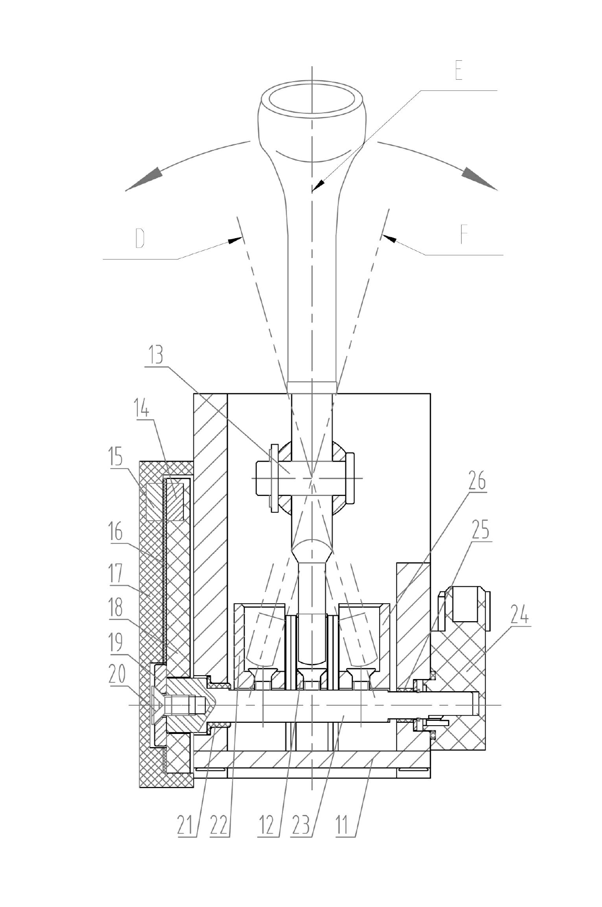
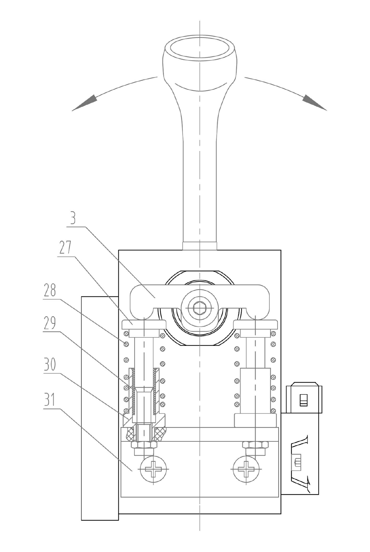
[0036] An electro-pneumatic shift handle mechanism, such as figure 1 — Figure 6 As shown, it includes a shift handle 1, a position selection swing arm 3, a gear seat 4, a shift handle seat 5, a position selection shaft 7, a dial 8, a shift swing arm 18, and a shift shaft 23, wherein the shift handle 1 is connected with the dial head 8, and is connected with the position selection shaft 7 through the pin shaft 13, the position selection shaft 7 is fixed on the shift handle seat 5 through the gear seat 4, and a position selection sensor 10, a shift sensor 24, a gear A position warning device 33 and a voice prompt system 34, wherein the position selection sensor 10 is fixed on one side of the shift handle seat 5 an...


PUM


Abstract

The invention relates to an electric control pneumatic gear shifting handle mechanism, which comprises a gear shifting handle, a position selecting swing arm, a gear seat, a gear shifting handle seat, a position selecting shaft, a shifting block, a gear shifting swing arm, a gear shifting shaft, a position selecting sensor, a gear shifting sensor, a gear warning device, a voice prompt system, a gear shifting swing arm strong magnet and a gear shifting swing arm seat strong magnet, wherein the position selecting sensor is fixed on one side of the gear shifting handle seat and is connected with one end of the position selecting shaft; the gear shifting sensor is fixed on one side of the gear shifting handle seat and is connected with one end of the gear shifting shaft; and the gear warning device and the voice prompt system are arranged on a gear panel. In the gear shifting handle mechanism, the gear shifting operation habit of the conventional commercial automobile mechanical transmission is not changed; superior comfort can be achieved during operation of the gear shifting handle; gear shifting operation can be easily and conveniently realized; and the mechanism has a prompt effect on the gear, and also has the advantages of compact structure, short gear shifting distance, high safety and the like.

Description

technical field [0001] The invention relates to an automobile gearbox shifting mechanism, in particular to an electronically controlled pneumatic shifting handle mechanism suitable for commercial vehicles. Background technique [0002] At present, the transmission shift control device on various automobiles is composed of a shift handle, a gear selection rocker arm, a gear shift rocker arm, a gear selection shaft, a shift shaft and a shift paddle, etc. The shift handle is driven by wire drawing The gear selection rocker arm and the gear shift rocker arm control the position of the shift paddle to realize the gear shifting and gear selection of the automobile gearbox. Because the purely mechanical structure is easy to wear and tear, the service life is short, the mechanism is large, and it is laborious to operate. With the development of technology, more and more power-assisted shifting mechanisms are used, such as electronically controlled hydraulic and electronically contro...

Claims


Application Information

Patent Timeline
Patent Type & Authority Applications(China)
IPC IPC(8): F16H59/10F16H63/42
Inventor 杨柳李传武陈迎红刘昕
Owner RUILI GROUP RUIAN AUTO PARTS CO LTD
Why Eureka
Try Eureka