Anchor of warp knitting machine

A warp knitting machine and ground foot technology is applied in the field of ground foot in textile machinery such as warp knitting machine or other processing equipment, which can solve the problems of poor shock absorption effect and complex structure.

Inactive Publication Date: 2012-02-22
CHANGZHOU RUNYUAN WARP KNITTING MACHINERY
View PDF7 Cites 28 Cited by
  • Summary
  • Abstract
  • Description
  • Claims
  • Application Information

AI Technical Summary

Problems solved by technology

Although the foot of this structure has a certain shock-absorbing performance, ...

Method used


Image

  • Anchor of warp knitting machine
  • Anchor of warp knitting machine
  • Anchor of warp knitting machine

Examples


Embodiment approach

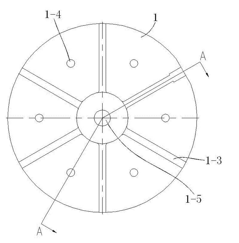
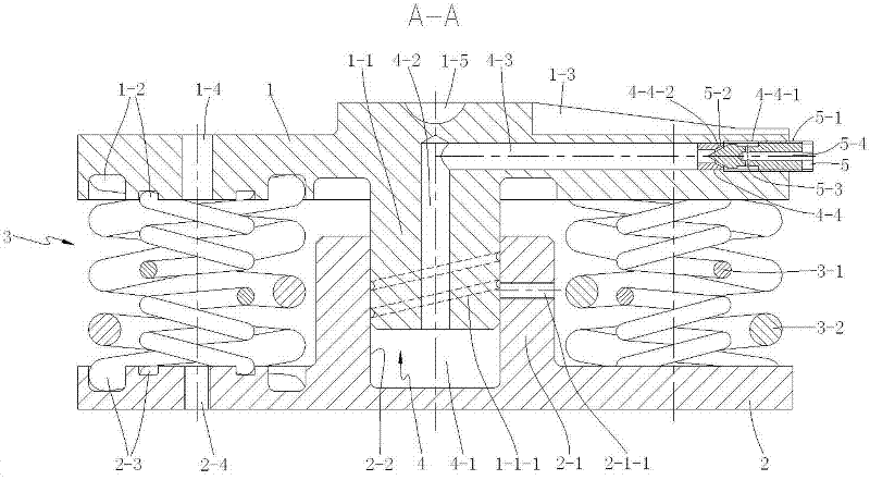
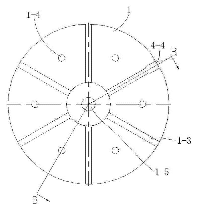
[0022] As a preferred embodiment of the present invention, the cross-sections of the upper and lower support plates 1 and 2 are circular, the first shaft part 1-1 is cylindrical, and the second shaft part 2-1 There is a cylindrical blind hole 2-2 that is slidably connected with the first shaft part 1-1 and is airtightly fitted; the airtight air chamber 4 is preferably composed of the first shaft part 1-1 and the cylindrical The first air chamber 4-1 formed between the blind holes 2-2, the first air chamber communicated with the first air chamber 4-1 and formed by the axial hole axially arranged along the first shaft part 1-1. Two air chambers 4 - 2 and a third air chamber 4 - 3 formed by radial holes communicated with the second air chamber 4 - 2 and arranged radially along the upper support plate 1 are formed. In the present invention, the airtight air cavity 4 can also be formed only by the first air cavity 4 - 1 formed between the first shaft portion 1 - 1 and the cylindric...


PUM


Abstract

The invention discloses an anchor of a warp knitting machine, which comprises an upper bearing plate and a lower bearing plate. The upper bearing plate is provided with a first shaft part extending downwards along the lower end face of the upper bearing plate. The lower bearing plate is provided with a second shaft part extending upwards along the upper end face of the lower bearing plate. The first shaft part and the second shaft part are connected in a sliding mode and are matched in an air-tight mode. Springs and a closed air cavity are arranged between the upper bearing plate and the first shaft part thereof and the lower bearing plate and the second shaft part thereof. Both the cross sections of the upper and lower bearing plates are of a round shape. The first shaft part is of a cylinder shape. The second shaft part is provided with a cylindrical blind hole. The closed air cavity is formed by a first air cavity, a second air cavity and a third air cavity, wherein the first air cavity is formed between the first shaft part and the cylindrical blind hole; the second air cavity is communicated with the first air cavity and is formed by an axial hole arranged along the axial direction of the first shaft part; and the third air cavity is communicated with the second air cavity and is formed by a radial hole arranged along the radial direction of the upper bearing plate. The anchor of the warp knitting machine has excellent vibration reduction performance, can bear a larger load, can be used for preventing a machine bed from being turned over and can be popularized and applied in equipment such as the warp knitting machine and the like.

Description

technical field [0001] The invention relates to an anchor, in particular to an anchor applied to textile machines such as warp knitting machines or other processing equipment. Background technique [0002] Existing textile machinery, especially the feet used by warp knitting machines usually adopt the following two structures. The first one is as a Chinese utility model patent, the patent number is ZL201020114221.9, and the name is a kind of base foot disclosed A structure comprising an upper plate and a lower plate arranged parallel to the upper plate, a cavity is formed between the upper plate and the lower plate, and bolts mounted on the lower plate extend into the cavity through the lower plate cavity. Although the feet of this structure can withstand the large static load force generated by the equipment due to its own weight and the dynamic load force generated by the vibration during operation, it cannot reduce the vibration generated by the equipment during operatio...

Claims


Application Information

Patent Timeline
IPC IPC(8): F16M7/00F16F15/023F16F15/06F16F3/06
Inventor 王占洪莫卫萍刘莉萍
Owner CHANGZHOU RUNYUAN WARP KNITTING MACHINERY
Why Eureka
Try Eureka