Pneumatic high pressure oiler with gas group cover

A pneumatic high-pressure oiler technology, applied in the field of butter machines, can solve the problems of easy wear and tear of the reversing air distribution mechanism, high strength of the operator, and damage to other accessories, and achieves convenient and easy connection and disassembly, short disassembly time, and lightening The effect of labor intensity

Active Publication Date: 2014-10-29
ZHEJIANG REFINE WUFU AIR TOOLS
View PDF8 Cites 2 Cited by
  • Summary
  • Abstract
  • Description
  • Claims
  • Application Information

AI Technical Summary

Problems solved by technology

[0002] At present, most of the known butter machines use the reciprocating motion of pneumatic components to drive the lifting mechanism to increase the oil pressure, and oil the parts that need to be oiled through the oil gun. The reversing air distribution mechanism in the oiler is easy to wear, but the existing Most of the air distribution mechanism and the shell of the pneumatic high-pressure oiler are an integral structure. In this way, when the accessories in the air distribution mechanism are faulty or need to be overhauled, the pneumatic high-pressure oiler must be completely disassembled. The advantages are: first, the overall disassembly and assembly will cause unnecessary damage and damage to other accessories; second, it will cause high strength for the operator and inconvenient maintenance; third, it will take a long time for maintenance

Method used


Image

  • Pneumatic high pressure oiler with gas group cover
  • Pneumatic high pressure oiler with gas group cover
  • Pneumatic high pressure oiler with gas group cover

Examples


Embodiment Construction

[0029] Below in conjunction with accompanying drawing, the present invention will be further described with specific embodiment, see Figure 1-10 :

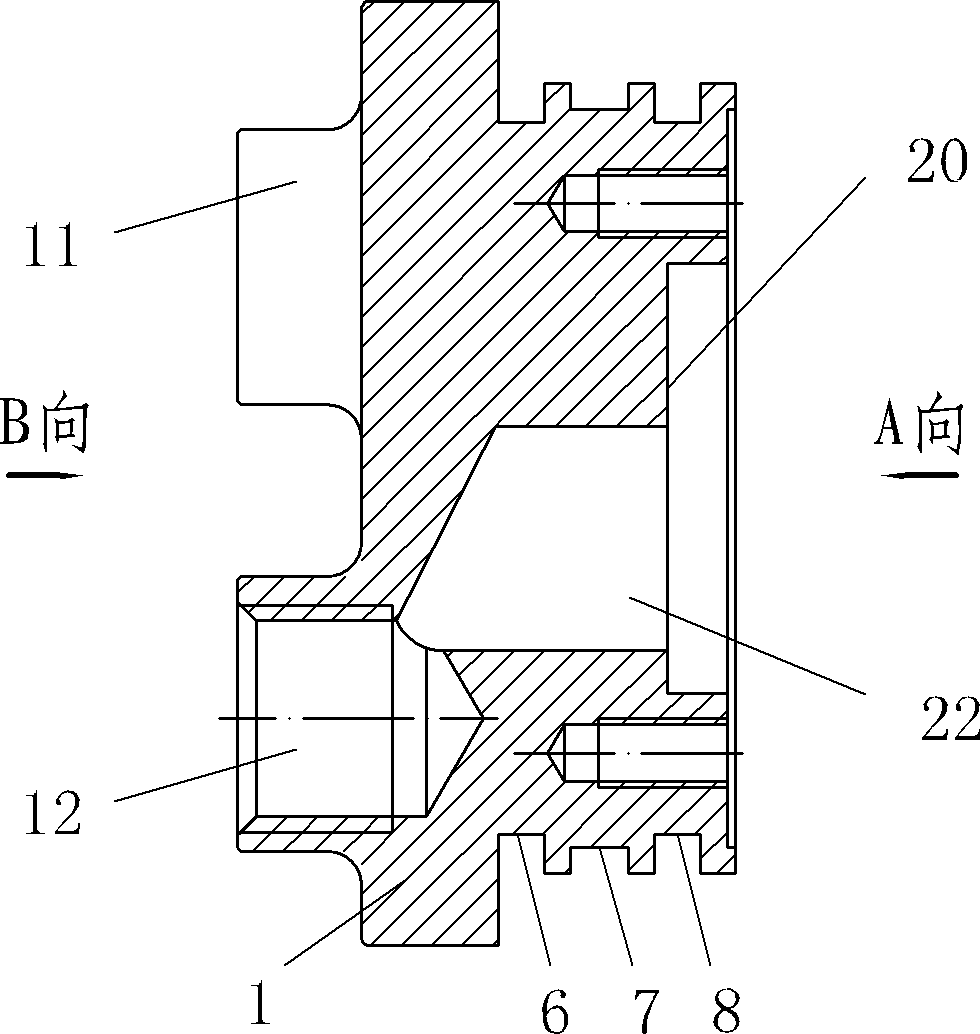
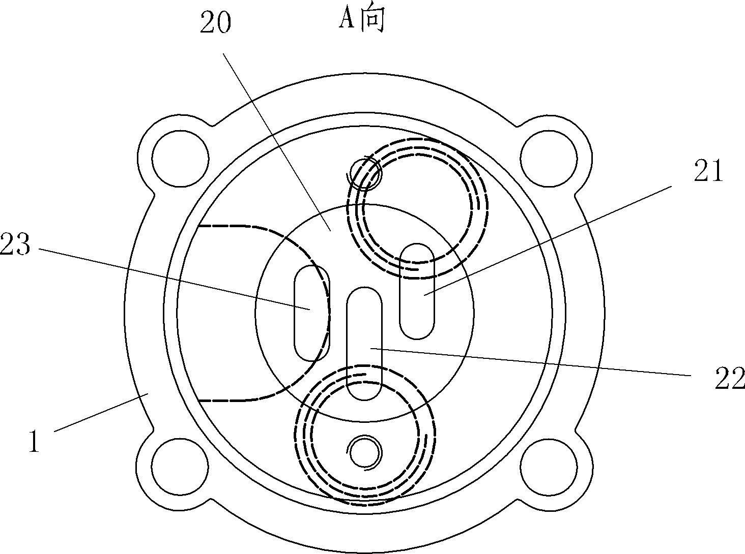
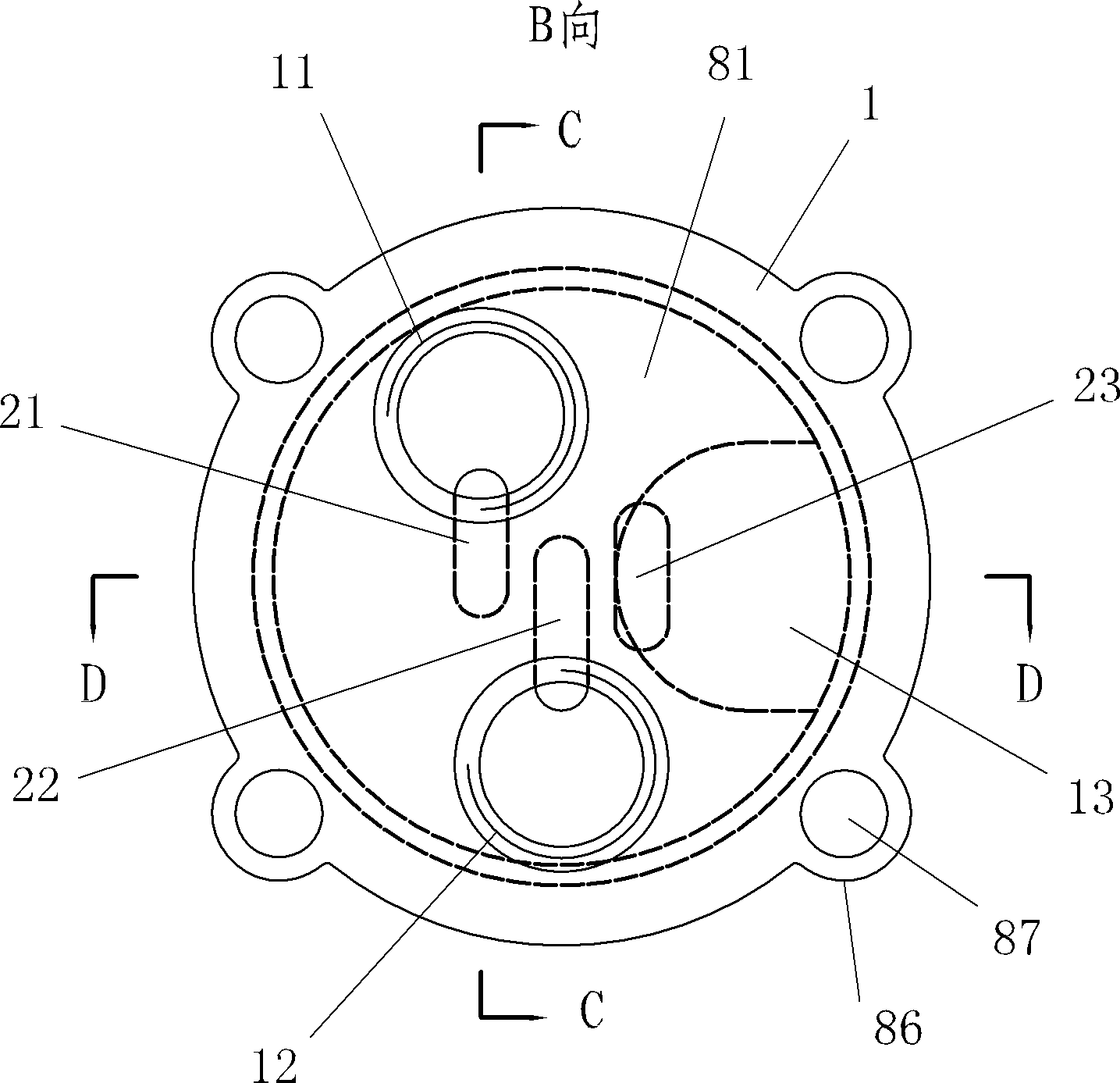
[0030] The gas distribution group cover of the pneumatic high-pressure oiler is provided with an installation part 1 in the middle of the main body of the distribution gas group cover, a conduit joint 11 and a silencer installation joint 12 are arranged side by side on one side, and a cylinder is provided on the other side. Three circles of annular grooves (6, 7, 8) are arranged on the cylindrical surface of the cylinder, a cylindrical groove 20 is arranged in the center on the circular surface 80, and three strip holes (21, 22, 23) are axially arranged in the groove 20 , the middle strip hole 22 communicates with the center hole of the muffler installation joint 12, the strip hole 21 on one side communicates with the center hole of the conduit joint 11, and the strip hole 23 on the other side communicates with the circular groov...


PUM


Abstract

The invention belongs to the technical field of butter machines, and in particular relates to a gas distribution group cover of a pneumatic high pressure oil injector. The middle part of a gas distribution group cover main body is provided with an installation part, one side of the gas distribution group cover main body is provided with a gas outlet joint and a silencer installation joint side by side, and the other side of the gas distribution group cover main body is provided with a cylinder; a cylindrical surface of the cylinder is provided with three circles of annular grooves, and a cylindrical groove is formed in the middle on the cylindrical surface; and three strip holes are axially formed in the groove, the strip hole in the middle is communicated with a central hole of the silencer installation joint, the strip hole on one side is communicated with a central hole of the gas outlet joint, and the strip hole on the other side is communicated with a groove radially formed on the middle annular groove on the cylindrical surface. The invention has the advantages that: the gas distribution group cover main body has an integrated structure and high work efficiency and is convenient to disassemble; a silencer arranged at the silencer installation joint of the gas distribution group cover main body is convenient to assemble and disassemble, so that the oil injector is low in noise; the internal gas circuit of the oil injector is short and simple; and the cover is suitable to be used as gas distribution group covers of various pneumatic high pressure oil injectors.

Description

technical field [0001] The invention belongs to the technical field of butter machines, in particular to a gas distribution group cover of a pneumatic high-pressure oiler. Background technique [0002] At present, most of the known butter machines use the reciprocating motion of pneumatic components to drive the lifting mechanism to increase the oil pressure, and oil the parts that need to be oiled through the oil gun. The reversing air distribution mechanism in the oiler is easy to wear, but the existing Most of the air distribution mechanism and the shell of the pneumatic high-pressure oiler are an integral structure. In this way, when the accessories in the air distribution mechanism are faulty or need to be overhauled, the pneumatic high-pressure oiler must be completely disassembled. The advantages are: first, the overall disassembly and assembly will cause unnecessary damage and damage to other accessories; second, the strength of the operator is high and maintenance i...

Claims


Application Information

Patent Timeline
Patent Type & Authority Patents(China)
IPC IPC(8): F16N13/16
Inventor 潘灵钢
Owner ZHEJIANG REFINE WUFU AIR TOOLS
Why Eureka
Try Eureka