
Fastener stringer, slide fastener, and objects with attached fasteners

A technology of zipper teeth and zipper tape, applied in the direction of sliding fastener components, applications, fasteners, etc., can solve problems such as electromagnetic wave gap leakage

Active Publication Date: 2015-04-08
YKK CORP
View PDF11 Cites 0 Cited by
  • Summary
  • Abstract
  • Description
  • Claims
  • Application Information

AI Technical Summary

Problems solved by technology

[0020] However, in such conventional slide fasteners and slide fastener chains, in a state in which the left and right fastener elements are meshed, there is formed between the left and right fastener elements and between the fastener elements adjacent to each other in the tape length direction. lots of tiny gaps
[0021] Therefore, in conventional slide fasteners and fastener chains, even if the fastener tape and the fastener elements are conductive in order to obtain an electromagnetic wave shielding function, there is still a problem that electromagnetic waves leak through a large number of gaps formed in the meshed element rows.

Method used


Image

  • Fastener stringer, slide fastener, and objects with attached fasteners
  • Fastener stringer, slide fastener, and objects with attached fasteners
  • Fastener stringer, slide fastener, and objects with attached fasteners

Examples


Embodiment 1

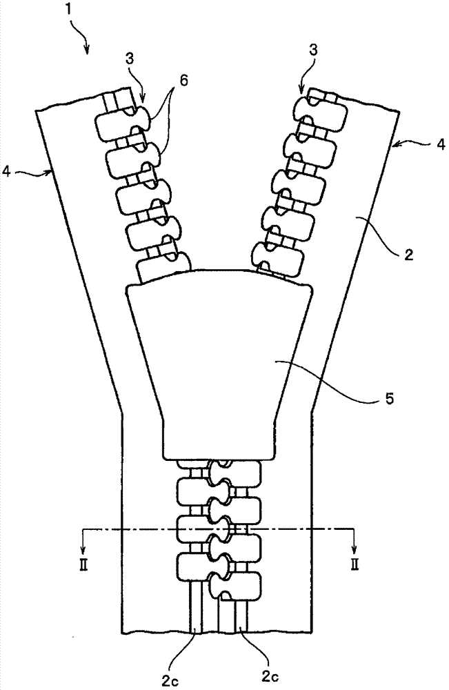
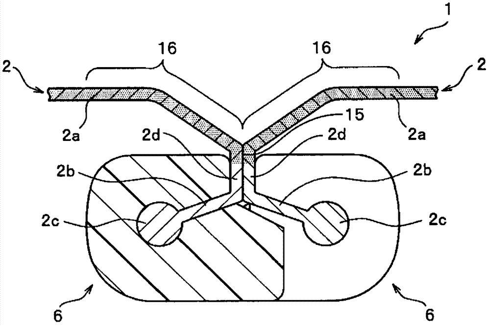
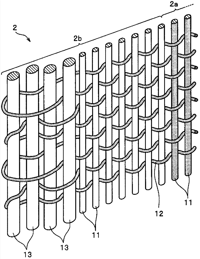
[0070] figure 1 It is a front view showing the slide fastener of Example 1 of the present invention, figure 2 yes figure 1 The II-II line sectional view shown. in addition, image 3 is a partial perspective view schematically showing the weaving structure of the fastener tape in the slide fastener, Figure 4 It is a perspective view which shows the fastener element used for this slide fastener.

[0071] In addition, in this embodiment 1 and the embodiment 2 to embodiment 5 described later, the tape length direction of the fastener tape is the front-rear direction, the tape width direction is the left-right direction, and the direction orthogonal to the front-rear direction and the left-right direction ( Or with the front and back direction) for the up and down direction to explain each zipper.

[0072] The slide fastener 1 of the present embodiment 1 is constituted as a so-called hidden slide fastener, and has: a pair of left and right fastener stringers 4 formed by at...

Embodiment 2

[0097] Figure 7 It is a sectional view which shows the slide fastener which concerns on Example 2 of this invention. In addition, in the second embodiment and the third to fifth embodiments described later, members having the same configurations as those described in the above-mentioned embodiments are denoted by the same reference numerals, and thus descriptions thereof are omitted.

[0098] The slide fastener 41 of the present embodiment 2 is constituted as a hidden slide fastener, and has: a pair of left and right fastener stringers 44 formed by attaching an element row 43 to a fastener tape 42; The unillustrated pull head on 43. Moreover, each fastener stringer 44 on either side has the fastener tape 42 and the coil-shaped continuous fastener element 46 which forms the element row 43 attached to this fastener tape 42, respectively.

[0099] The left and right fastener tapes 42 in this Example 2 each have a tape main body part 42a and an element attaching part 42b arrang...

Embodiment 3

[0108] Figure 8 It is a front view showing the slide fastener of Example 3 of the present invention, Figure 9 yes Figure 8 IX-IX line sectional view shown. in addition, Figure 10 It is a perspective view which shows the regulation member used for this slide fastener.

[0109] In the slide fastener 51 of the present embodiment 3, the inner surface of the fastener element mounting portion 42b of the fastener tape 42 bent into a U shape (the tape on the opposite side to the tape surface of the fastener element mounting portion 42b where the continuous fastener elements 46 are sewn) surface), there is a restriction member 52 that is sewn together with the continuous fastener element 46 by the double-thread loop stitching of the sewing thread 48, and the configuration other than the restriction member 52 is substantially the same as that of the aforementioned embodiment 2. .

[0110] Such as Figure 10 As shown, the restricting member 52 of the third embodiment has: a plu...


PUM


Abstract

For fastener stringers (4, 44, 64), paired left and right fastener tapes (2, 42, 62) comprise a main body of the tape (2a, 42a, 62a) and element attachment part (2b, 42b, 62b) that is disposed on one edge of the main body of the tape (2a, 42a, 62a). A row of elements (3, 43, 63) is attached to the element attachment part (2b, 42b, 62b). Electrically conductive yarn is used for the main structural yarn lines (11, 12) that configure the fastener tapes (2, 42, 62), and the fastener tapes (2, 42, 62) have conductivity that can shield electromagnetic waves. Moreover, the pair of fastener tapes (2, 42, 62) have electrically conductive tape-contacting parts (16, 49, 62c) that closely contact the fastener tape (2, 42, 62) on the other side when the rows of elements (3, 43, 3) are interlocked, and the rows of elements (3, 43, 63) in an engaged state are covered by the tape-contacting parts (16, 49, 62c) when the tape-contacting parts (16, 49, 62c) closely contact each other. Such fastener stringers (4, 44, 64) can prevent leakage of electromagnetic waves from the rows of elements (3, 43, 63) in an engaged state and can reliably shield electromagnetic waves.

Description

technical field [0001] The present invention relates to a fastener stringer capable of shielding (shielding) electromagnetic waves, a slide fastener constructed using the fastener stringer, and a fastener attachment to which the slide fastener is attached. Background technique [0002] In recent years, information and communication equipment and digital electronic equipment have been popularized, but on the other hand, the problem of electromagnetic waves emitted by these equipment has also been paid attention to. For example, it is known that electromagnetic waves emitted from communication equipment etc. cause various equipment to malfunction or fail. [0003] In addition, since electromagnetic waves are emitted from information devices such as OA devices, for example, by receiving electromagnetic waves from such information devices externally, personal information and corporate confidential matters can be stolen. In this way, electromagnetic waves cause various disadvant...

Claims


Application Information

Patent Timeline
Patent Type & Authority Patents(China)
IPC IPC(8): A44B19/04A44B19/34
CPCA44B19/34
Inventor 宫崎祐一小岛昌芳高林康之
Owner YKK CORP
Learn More