
Winding machine

A technology of winding machine and roller blind, which is applied in thin material handling, conveying filamentous materials, transportation and packaging, etc., can solve problems such as insufficient stability, and achieve the effect of improving guidance and stable guidance.

Active Publication Date: 2020-06-16
OERLIKON TEXTILE GMBH & CO KG
View PDF12 Cites 0 Cited by
  • Summary
  • Abstract
  • Description
  • Claims
  • Application Information

AI Technical Summary

Problems solved by technology

However, the stability of such a shielding mechanism in the extended state is insufficient, which is particularly noticeable in the case of elongated overhanging winding spindles with many bobbins.

Method used


Image

  • Winding machine
  • Winding machine
  • Winding machine

Examples


Embodiment Construction

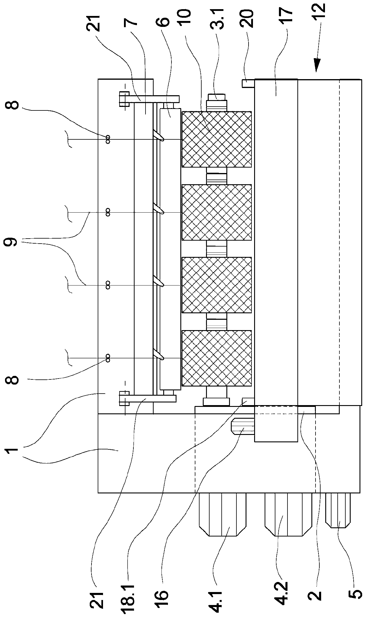
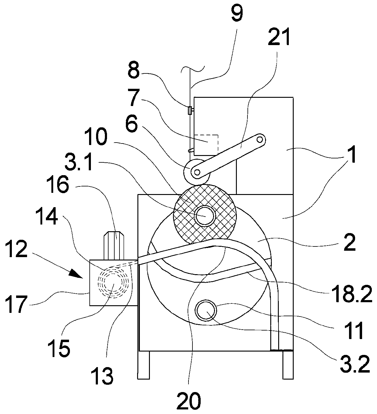
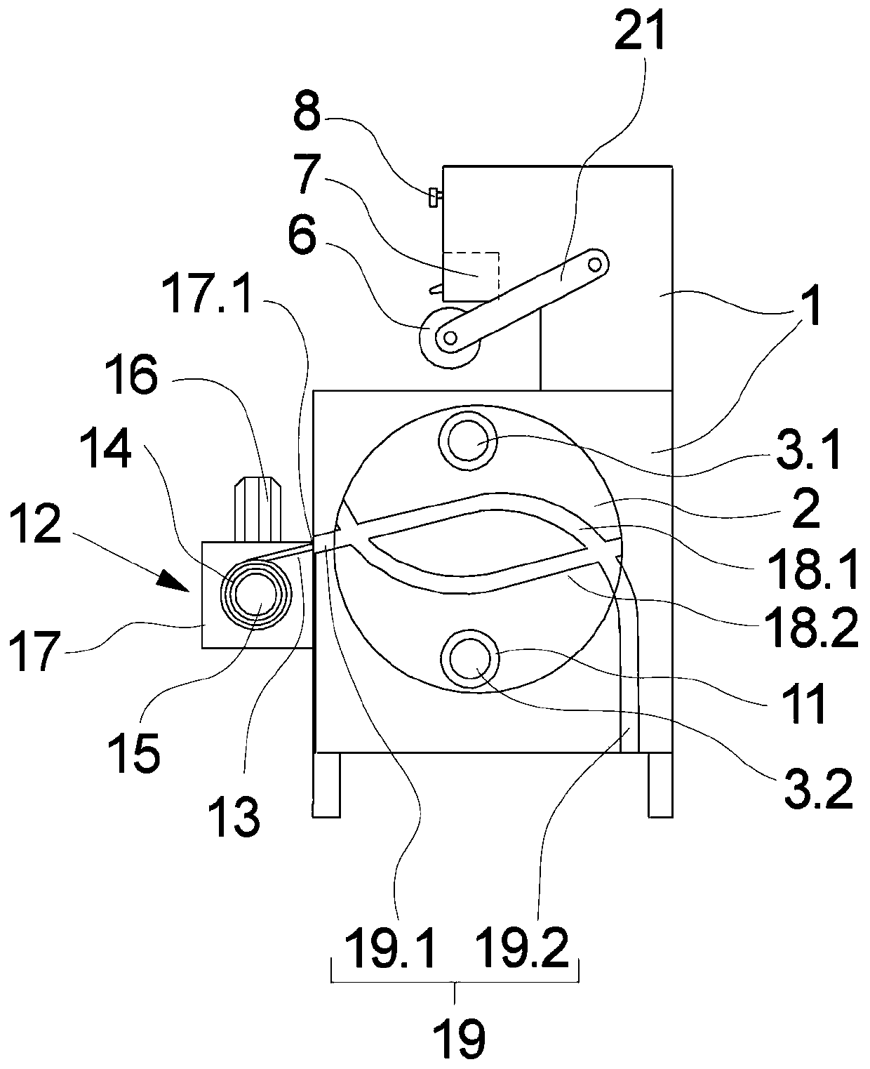
[0022] exist figure 1 and figure 2 An embodiment of the winding machine of the present invention is shown in several views in FIG. exist figure 1 A side view of this embodiment is shown in , while figure 2 Its front view is shown. An embodiment of the winding machine of the invention is shown in an operating condition in which sheets of yarns of a plurality of yarns are simultaneously wound into bobbins. The following pairs figure 1 and figure 2 The description of the embodiments refers to both figures unless explicit reference is made to one of them.

[0023] This embodiment has a frame 1 in which a winding turret 2 is rotatably mounted. The rotational movement of the winding carousel 2 in the machine frame 1 is carried out by a carousel drive 5 . Two winding spindles 3 . 1 , 3 . 2 , which are arranged offset by 180° relative to each other, are held overhanging on the winding turret 2 . Two spindle drives 4.1, 4.2 are assigned to the winding spindles 3.1, 3.2 resp...


PUM


Abstract

The invention relates to a winding machine for winding threads with a rotatable winding turret, which carries two long projecting winding spindles for alternately winding the threads into bobbins. A shielding device is assigned to the winding spindles, and has at least one movable shielding means for covering fully wound bobbins on one of the winding spindles with respect to the other winding spindles, the shielding means being formed by a shielding roller blind held on a rotatable winding roller. For safe guidance with minimal free space, according to the invention, the shielding roller blindis assigned at least one turret guide attached to the winding turret, which cooperates with at least one frame guide on a machine frame for guiding the shielding roller blind.

Description

technical field [0001] The present invention relates to winding machines. Background technique [0002] For winding synthetic yarns, usually winders are used, which allow the yarn to be wound continuously into bobbins. For this purpose, the winding machine has two winding spindles, which are held on a rotatably mounted winding turret and are thus held alternately in the working area for winding at least one yarn and for removing the wound coil. In the changing area of ​​the bobbins. Thus, one or more yarns can, for example, be continuously taken up and wound into bobbins in a melt-spinning plant. The winding spindle is preferably held overhanging on the winding turret, so that the rolled bobbin can be removed at the free end of the winding spindle. At this time, it is ensured that the movable yarn end held on the bobbin in the changing area does not enter the working area of ​​the newly wound bobbin. In this regard, it is known to guide a shutter between the winding spin...

Claims


Application Information

Patent Timeline
IPC IPC(8): B65H54/20B65H54/44B65H54/28B65H54/70B65H67/056B65H57/14
CPCB65H54/20B65H54/44B65H54/28B65H54/70B65H67/056B65H57/14B65H2701/31B65H67/048B65H54/72
Inventor A·哈米德R·沃斯
Owner OERLIKON TEXTILE GMBH & CO KG
Learn More