
Circuit and method for generating self-adapting silicon-controlled light regulating signal

A silicon dimming and self-adaptive technology, applied in the direction of lamp circuit layout, light source, electric light source, etc., can solve the problems of AC input waveform phase cut to zero, LED output current not completely adjusted to zero, LED can not achieve dimming and other problems , to achieve the effect of reducing the LED output current and LED brightness, and increasing the dimming range

Active Publication Date: 2012-02-29
HANGZHOU SILAN MICROELECTRONICS
View PDF6 Cites 7 Cited by
  • Summary
  • Abstract
  • Description
  • Claims
  • Application Information

AI Technical Summary

Problems solved by technology

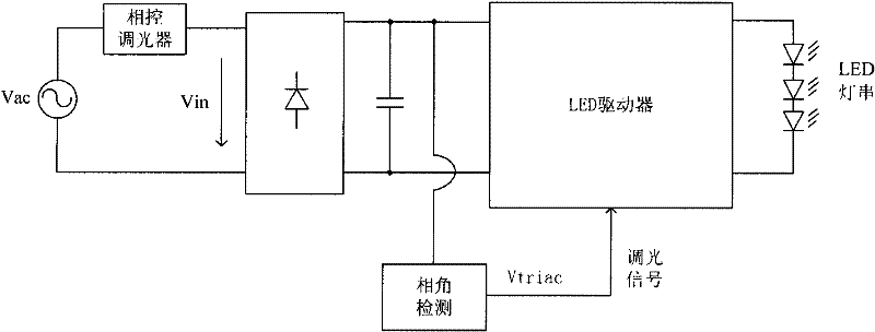
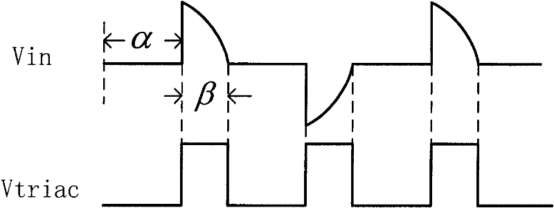
[0003] There is a minimum conduction angle in the traditional thyristor dimmer, that is, before the dimming angle of the thyristor dimmer is adjusted to the maximum and it is completely turned off, the AC input waveform cannot be completely phase-cut to zero.
When the SCR is at the minimum conduction angle, there is still input power, which causes the output current of the LED to not be completely adjusted to zero, and the LED cannot be dimmed in a full range, and the higher the input voltage, the greater the input power, and the minimum output current of the LED bigger

Method used


Image

  • Circuit and method for generating self-adapting silicon-controlled light regulating signal
  • Circuit and method for generating self-adapting silicon-controlled light regulating signal
  • Circuit and method for generating self-adapting silicon-controlled light regulating signal

Examples


Embodiment Construction

[0034] The content of the present invention will be described in detail below in conjunction with the block diagram of the present invention and the schematic diagrams of specific embodiments.

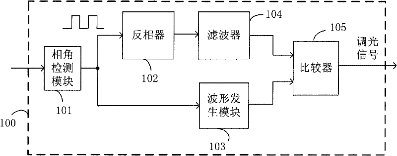
[0035] image 3 It is a schematic block diagram of the adaptive thyristor dimming signal generating circuit of the present invention. Such as image 3 As shown, the adaptive thyristor dimming signal generating circuit of the present invention includes:

[0036] Phase angle detection module 101, described phase angle detection module input 101 is the conduction phase angle signal of AC input signal, output connects the input end of inverter 102 and waveform generation module 103; Phase angle detection module 101 passes through detection AC input The conduction phase angle signal of the signal generates a rectangular wave signal with a frequency equal to twice the frequency of the AC input voltage, a pulse width equal to the width of the AC input voltage after the phase is cut, and a f...


PUM


Abstract

The invention discloses a circuit and method for generating a self-adapting silicon-controlled light regulating signal. The circuit comprises a phase angle detection module, an inverter, a filter and a comparer. The circuit can generate a corresponding light regulating signal according to a conducting phase angle signal of an input signal. The circuit and the method disclosed by the invention have the advantages that: by the improvement of traditional silicon-controlled light regulating signal, the width of the light regulating signal corresponding to controlled silicon in the minimum conduction angle is reduced, thus the output current of a light-emitting diode (LED) and the brightness of the LED are reduced; and the influence on the width of the light regulating signal when the silicon controlled conduction angle is larger is less, thus the light regulating range is increased.

Description

technical field [0001] The invention belongs to the technical field of switching power supplies, and relates to a thyristor dimming signal generating circuit and method. Background technique [0002] LED is a new type of energy-saving lighting equipment. It requires much less power than incandescent lamps to produce the same light. Compared with energy-saving lamps and incandescent lamps, LEDs have the advantages of small size and less damage. The brightness of the LED is directly related to the current flowing through it. In lighting applications, a driver is needed to convert the mains power into a constant current output or a constant voltage output to drive the LED. In some applications, the function of adjusting the brightness of the LED is required, that is, the dimming function. At present, a traditional method is to directly replace traditional lighting fixtures, such as incandescent lamps, with LEDs. Therefore, the dimming of LEDs often directly uses the original t...

Claims


Application Information

Patent Timeline
IPC IPC(8): H05B37/02
Inventor 谢小高叶美盼蔡拥军吴建兴
Owner HANGZHOU SILAN MICROELECTRONICS
Learn More