Axial turbomachine rotor having blade cooling

An axial-flow turbine and rotor technology, which is applied to the support elements of blades, mechanical equipment, engine elements, etc., can solve the problems of expensive manufacturing and installation of additional components, and achieve the effect of saving resources, high service life, and effective cooling

Inactive Publication Date: 2012-02-29
SIEMENS AG
View PDF4 Cites 0 Cited by
  • Summary
  • Abstract
  • Description
  • Claims
  • Application Information

AI Technical Summary

Problems solved by technology

However, additional components are expensive to manufacture and install

Method used


Image

  • Axial turbomachine rotor having blade cooling
  • Axial turbomachine rotor having blade cooling
  • Axial turbomachine rotor having blade cooling

Examples


Embodiment Construction

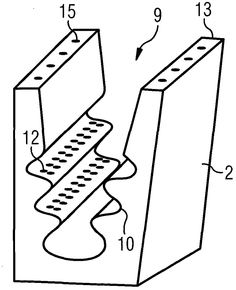
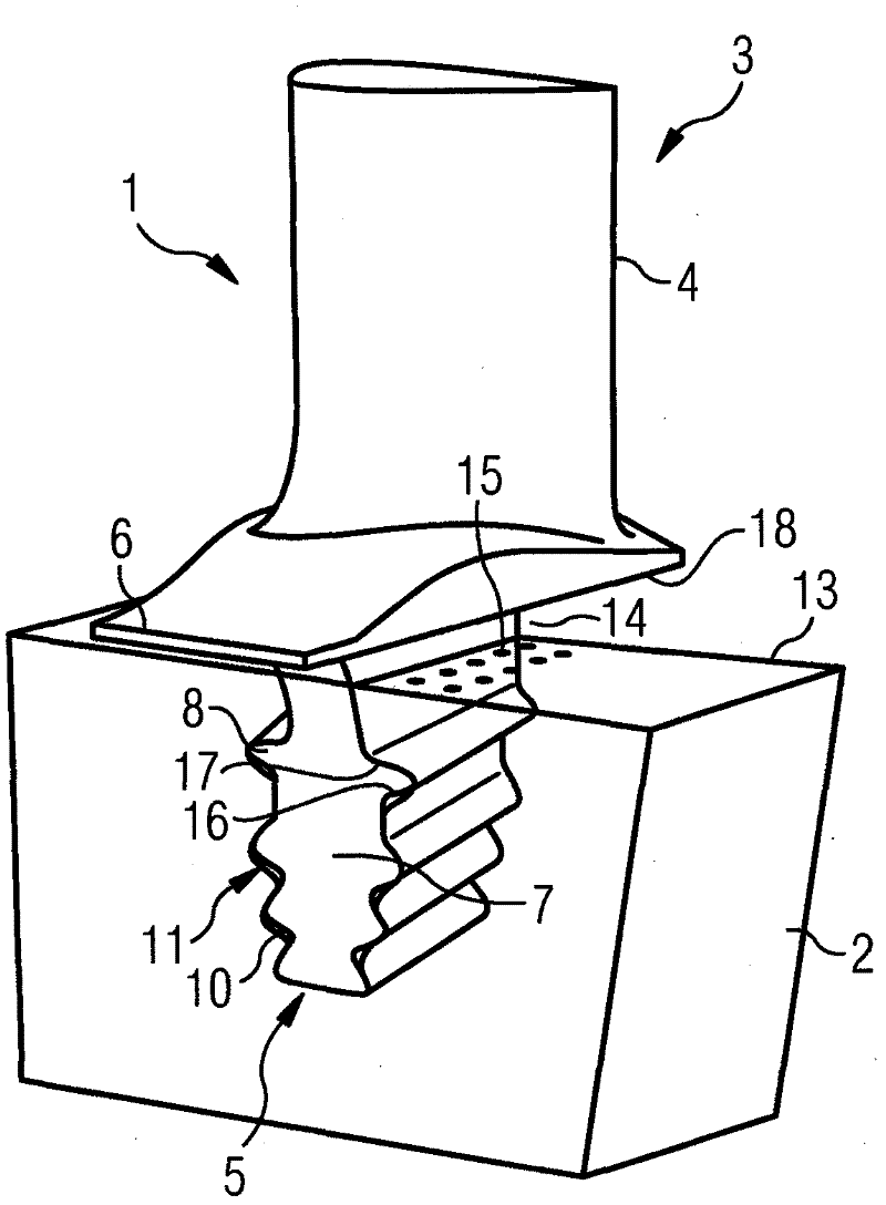
[0013] as in figure 1 and 2 As can be seen in the figure, the axial turbine rotor 1 has a disk arranged rotationally symmetrically about the axis of rotation of the axial turbine rotor 1 . Arranged on the outer edge 13 of the disk 2 are a plurality of rotor blades 3 which adjoin over the circumference of the disk 2 , wherein the rotor blades 3 form a rotor blade ring. Each moving blade 3 has an airfoil 4 by means of which the moving blade 3 interacts with the working fluid of the axial turbine rotor 1 . The airfoil 4 is arranged radially outwardly on the disk 2 , wherein the moving blade 3 has a blade root 5 at the radially inner end of the airfoil 4 , by means of which the airfoil 4 is fastened to the disk. 2 on. Between the airfoil 4 and the blade root 5, a blade platform 6 is formed on the moving blade 3, said blade platform extending in the axial direction and the circumferential direction of the axial turbine rotor 1, wherein the radially outer side of the blade platfo...


PUM


Abstract

The invention relates to an axial turbomachine rotor comprising a rotor disk (2) and a rotor blade ring, which comprises a plurality of rotor blades (3), which each comprise a blade root (5), with which the rotor blade (3) is fixed radially outward on the rotor disk (2), wherein the blade root (5) is engaged with the rotor disk (2) at the outer edge of the rotor disk in a form-closed manner in such a way that during operation of the axial turbomachine rotor (1), a gap is formed between the rotor blade (3) and the rotor disk (2) at a predetermined surface area of the rotor disk (2), in which area a plurality of impingement cooling openings (12, 15) is arranged, through which a cooling medium can flow from the interior of the rotor disk (2) into the gap (11, 14), whereby the rotor blade (3) can be cooled using the cooling medium by means of impingement cooling by the cooling medium.

Description

technical field [0001] The invention relates to an axial turbine rotor with blade cooling, in particular to an axial turbine rotor with a blade ring consisting of a plurality of moving blades which can be cooled by means of impingement cooling. Background technique [0002] Turbomachines, such as gas turbines, have a compressor and a turbine, which are coupled via a rotor. The rotor has moving blades for the compressor and moving blades for the turbine, in which work is performed by means of the working fluid in the compressor and work is obtained from the working fluid in the turbine. The working fluid is heated upstream of the turbine, so that the components of the turbine are exposed to high temperature loads. Conventionally, the rotor is provided with a disk which is threaded on the shaft and which has moving blades forming a blade ring each on its outer edge. Due to the high mechanical and thermal loads, the service life of the disks and rotor blades is limited. As a...

Claims


Application Information

Patent Timeline
Patent Type & Authority Applications(China)
IPC IPC(8): F01D5/08F01D25/12
CPCF01D5/087F01D25/12F05D2260/201
Inventor 法蒂·艾哈迈德
Owner SIEMENS AG
Why Eureka
Try Eureka