Laminated Iron Core

一种叠铁芯、铁芯的技术,应用在磁路形状/式样/结构、制造电动发电机、电气元件等方向,能够解决马达铁芯保持力下降、马达铁芯变形等问题,达到防止磁特性的劣化、压力加工容易、提高材料利用率的效果

Inactive Publication Date: 2012-02-29
MITSUI HIGH TEC INC
View PDF11 Cites 9 Cited by
  • Summary
  • Abstract
  • Description
  • Claims
  • Application Information

AI Technical Summary

Problems solved by technology

[0002] In the above-mentioned laminated core (motor core) called "bent core", a connecting portion connecting adjacent divided laminated cores is formed In the outermost peripheral part of the iron core (specifically, the yoke part), but if the connection part is located at the outermost peripheral part of the yoke, the connection part bent when formed into a ring protrudes outward from the outer periphery of the core, Therefore, there is a problem that the holding force of the motor core decreases due to interference with the case, or the motor core itself deforms.

Method used


Image

  • Laminated Iron Core
  • Laminated Iron Core
  • Laminated Iron Core

Examples


Embodiment Construction

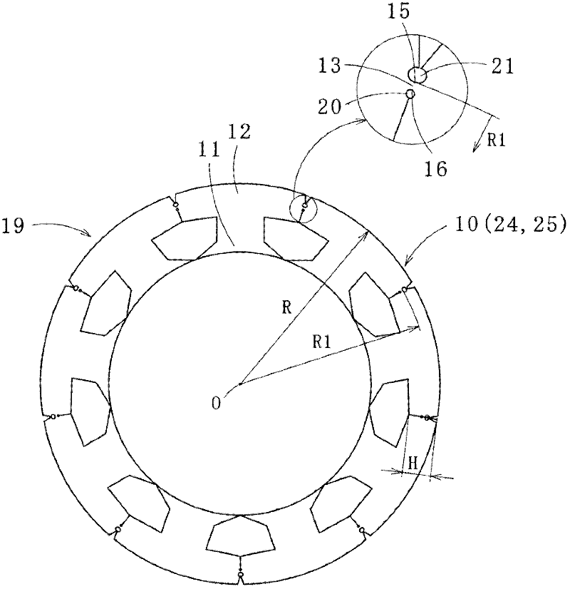
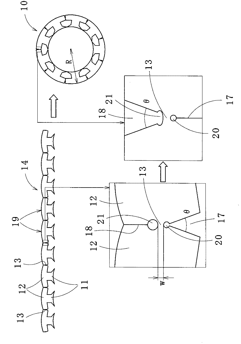
[0044] figure 1 A laminated iron core 10 according to a first embodiment of the present invention is shown. The laminated core 10 is the stator core of the motor, such as figure 2 As shown, the linear connection split core piece 14 connects the plurality of split yoke pieces 12 divided for each magnetic pole piece 11 with the bendable connection portion 13 , and the linear connection split core piece 14 A predetermined number of sheets are stacked, and the connecting portion 13 is bent to form a ring shape.

[0045] here, as figure 1 , figure 2 As shown, the radially outer position 15 of the connection portion 13 is at least 3% (preferably at least 5%, more preferably at least 10%) of the radius R of the laminated core 10 inwardly. In addition, the radially inner position 16 of the connecting portion 13 is located away from the inner position of the divided yoke piece 12 to the outside by more than 40% (preferably 50% or more) of the width H of the divided yoke piece 1...


PUM


Abstract

Provided is a laminated iron core (10) that will improve the yield of materials, and prevent cracks or ruptures from being produced on iron core pieces, by easing the stress to be generated on coupling sections (13). Coupled divided-iron-core-pieces (14) to be used in assembling the laminated iron core (10) has, on the inner side in the radius direction of the coupling sections (13), V-shaped slots (17) with an opening angle of 360 / n, assuming the number of divided-iron-core-pieces (19) to be n, and which open towards the inner side in the radius direction; and also has, on the outer side in the radius direction of the coupling sections (13), separating sections (18) that separate mutually-adjacent, divided yoke-piece sections (12), which are located more on the outer side in the radius direction than the coupling sections (13). Furthermore, first through holes (20) having circular-arcs are formed on the end sections at the outer side in the radius direction of the V-shaped slots (17), which are in contact with the coupling sections (13); and second through holes (20), having arcs with a radius of curvature greater than the circular-arcs of the first through holes (20), are formed on the end sections at the inner side in the radius direction of the separating sections (18), which are in contact with the coupling sections (13).

Description

technical field [0001] The present invention relates to laminated cores generally called "bent cores" or laminated cores generally called "wound cores"; the laminated cores called "bent cores" are constructed such that That is, the connection split core pieces are connected by a bendable connection portion to the split yoke piece portions, and the split yoke piece portions are formed by dividing the yoke piece portions for each magnetic pole piece, and the connection split core pieces are stacked in predetermined pieces. After forming a linear laminated core by several numbers, it is bent at each connecting portion to form a ring shape; this laminated core called "wound core" is constructed in such a way that the connecting split core pieces can be bent. The connection part connects the divided yoke piece part which is formed by dividing the yoke piece part into one or a plurality of magnetic pole pieces, and the connected divided iron piece part is bent and wound at the conne...

Claims


Application Information

Patent Timeline
Patent Type & Authority Applications(China)
IPC IPC(8): H02K1/18
CPCB21D28/10B21D28/22H02K1/148H02K1/16H02K15/026H02K2213/03
Inventor 牧清久莲尾裕介荒添萌
Owner MITSUI HIGH TEC INC
Why Eureka
Try Eureka