Centrifugal clamping device

A technology of clamping device and centrifugal device, which is applied in the direction of positioning device, clamping, support, etc., can solve the problems of high clamping pressure, safety accidents, poor clamping and positioning, etc., and achieve the effect of improving quality

Inactive Publication Date: 2012-03-07
CHANGZHOU SHENGFA BULB FACTORY
View PDF4 Cites 10 Cited by
  • Summary
  • Abstract
  • Description
  • Claims
  • Application Information

AI Technical Summary

Problems solved by technology

[0002] In the field of mechanical processing, when the bar is turned or drilled, due to the poor clamping and positioning of the bar, the bar is easy to shake during the processing, which leads to the out-of-round processing surface or the concentricity of the drilled inner hole. Poor, visual inspection, there is no effective fixture to solve this common problem
However, when the existing tooling fixture is used to process long bars with deep holes, the clamped part is often the end of the hole, which leads to excessive clamping pressure when the clamp is clamped, and excessive clamping pressure will often cause deep holes. The hole is deformed, resulting in waste products, and the clamping pressure is small and closes, causing the bar to fly out during the processing, resulting in a safety accident

Method used


Image

  • Centrifugal clamping device
  • Centrifugal clamping device
  • Centrifugal clamping device

Examples


Embodiment Construction

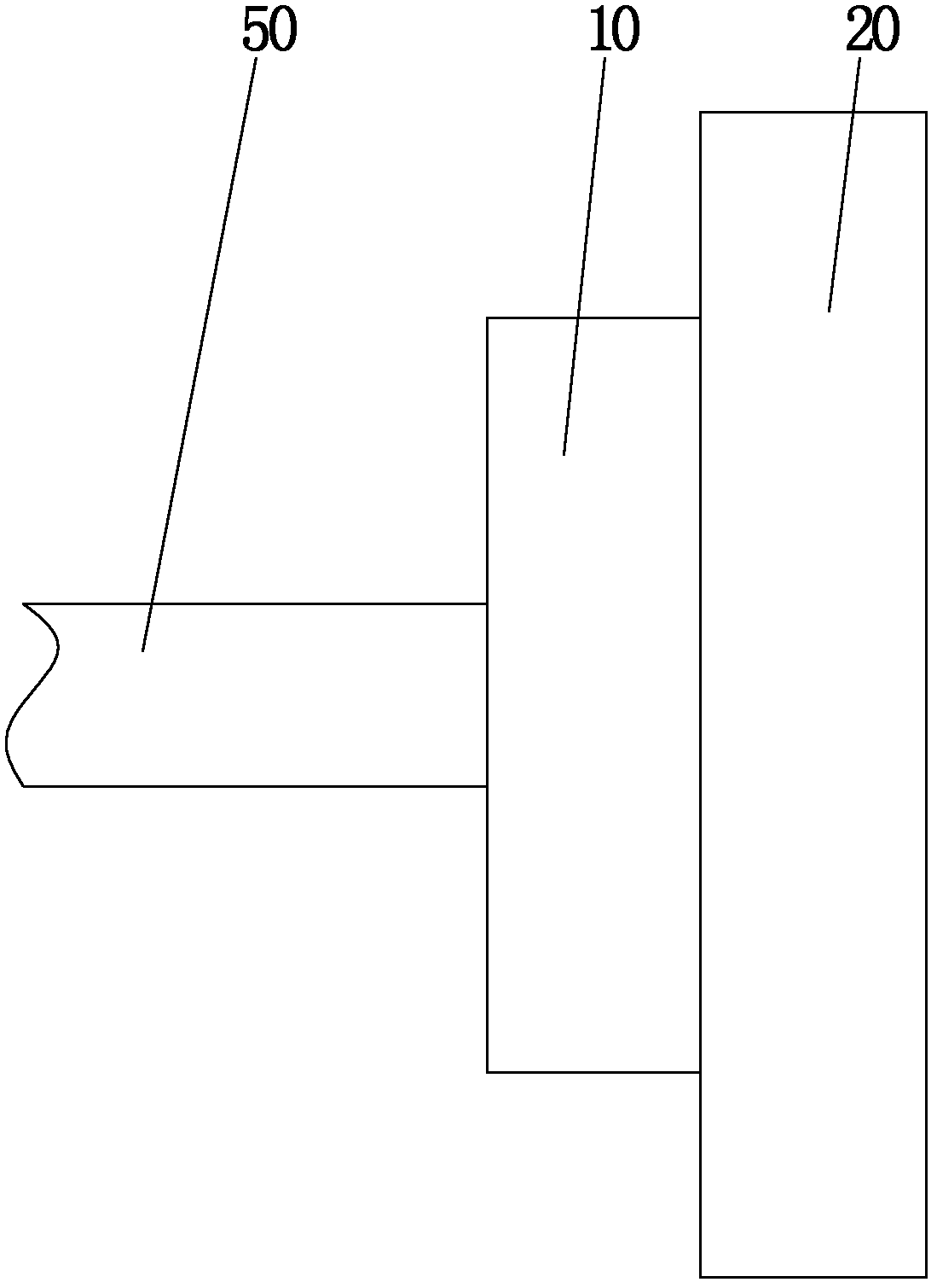
[0018] refer to figure 1 , the centrifugal clamping device of the present invention is mainly composed of a centrifugal device 10, a clamping device 20 and a locking device 30. The structure of each part and the combination between them will be described in detail below:

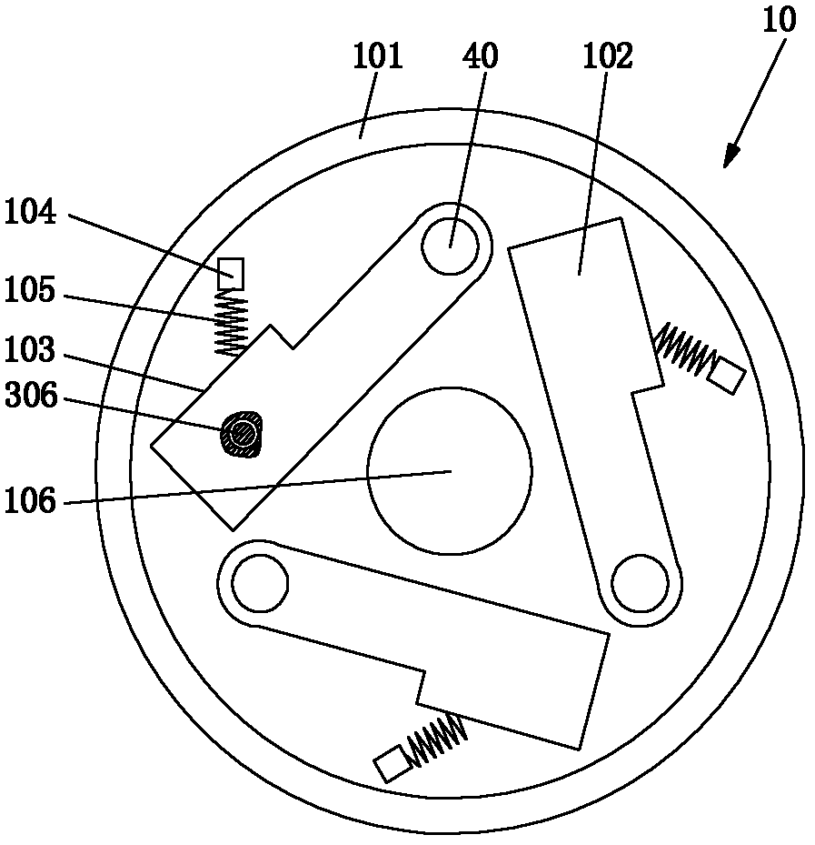
[0019] refer to figure 1 and figure 2 , the centrifugal device 10 includes a rotating disk 101 for generating centrifugal force, a plurality of centrifugal blocks 102, and a reset device. A central hole 106 for installing the power shaft 50 for generating torque is provided in the middle of the rotating disk 101, and an axial end surface of the rotating disk 101 is provided with a concave cavity, and the centrifugal block 102 and the reset device are installed in the concave cavity. The arrangement of the centrifugal blocks is as follows: each centrifugal block 101 is evenly distributed on the same axial end surface of the rotating disk, and one end of each centrifugal block 101 is circumferentially fixed...


PUM


Abstract

The invention discloses a centrifugal clamping device, which comprises a centrifugal device, wherein the centrifugal device comprises a rotary disk for generating a centrifugal force, a plurality of centrifugal blocks, a resetting device and a clamping device, wherein the centrifugal blocks are uniformly distributed on the same axial end surface of the rotary disk; one end of each centrifugal block is circumferentially fixed with a rotating shaft which is in sliding fit with the interior of an axial hole of the rotary disk; the other end of each centrifugal block is a free end and the centrifugal blocks are also connected with the resetting device; the clamping device comprises a supporting disk, a supporting rod and a centering and clamping part; a cavity for accommodating the rotary disk is arranged on one axial end surface of the supporting disk; the rotary disk can be rotatably matched with the interior of the cavity; the other end of the rotating shaft connected with the centrifugal blocks penetrates through the supporting disk, reaches the other axial end surface of the supporting disk and then is fixedly connected with one end of the supporting rod; and the centering and clamping part is fixedly arranged at the other end of the supporting rod. The centrifugal clamping device has the advantage of bringing convenience for clamping and positioning of bars.

Description

technical field [0001] The invention relates to a tooling in the technical field of machine tool processing, in particular to a centrifugal clamping device for clamping and positioning bars. Background technique [0002] In the field of mechanical processing, when the bar is turned or drilled, due to the poor clamping and positioning of the bar, the bar is easy to shake during the processing, which leads to the out-of-round processing surface or the concentricity of the drilled inner hole. Poor, visual inspection, there is no effective fixture to solve this ubiquitous problem. However, when the existing tooling fixture is used to process long bars with deep holes, the clamped part is often the end of the hole, which leads to excessive clamping pressure when the clamp is clamped, and excessive clamping pressure will often cause deep holes. The hole is deformed, resulting in waste products, and the clamping pressure is small and closes, causing the bar to fly out during the p...

Claims


Application Information

Patent Timeline
Patent Type & Authority Applications(China)
IPC IPC(8): B23Q3/12
Inventor 张顺
Owner CHANGZHOU SHENGFA BULB FACTORY
Why Eureka
Try Eureka