
Intelligent automatic management system for prevention of power theft

An automatic management and anti-stealing technology, applied in the direction of measuring electrical variables, measuring devices, instruments, etc., can solve the problem of zero line voltage of the electric energy meter, insufficient prevention of cutting off the metering system, difficulty in finding and searching by the power department, and no remote control Monitoring and other issues

Inactive Publication Date: 2012-03-07
于波涛
View PDF2 Cites 0 Cited by
  • Summary
  • Abstract
  • Description
  • Claims
  • Application Information

AI Technical Summary

Problems solved by technology

However, in this kind of measurement, the system wiring is changed, such as current circuit breaker, shunt, commutation, phase change, transformer reverse current reverse meter, phase line and neutral line interchange, voltage line open phase, phase change, and zero line with voltage Even cut off the metering system and other means to steal electricity, sometimes it is difficult for the power department to find and find
The metering anti-stealing system adopted by the existing power supply department mainly plays a certain role in preventing the user from changing the wiring of the metering system at will to cause line disconnection, shunting, and reversing, etc. It is insufficient, and the remote monitoring function has not been implemented at the same time

Method used


Image

  • Intelligent automatic management system for prevention of power theft
  • Intelligent automatic management system for prevention of power theft
  • Intelligent automatic management system for prevention of power theft

Examples


Embodiment Construction

[0019] Below in conjunction with accompanying drawing and embodiment, further elaborate the present invention. In the following detailed description, certain exemplary embodiments of the invention are described by way of illustration only. Needless to say, those skilled in the art would realize that the described embodiments can be modified in various different ways, all without departing from the spirit and scope of the present invention. Accordingly, the drawings and description are illustrative in nature and not intended to limit the scope of the claims.

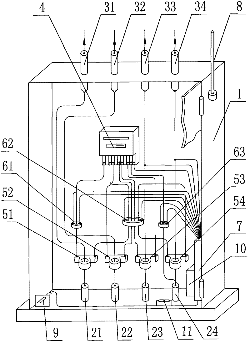
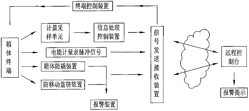
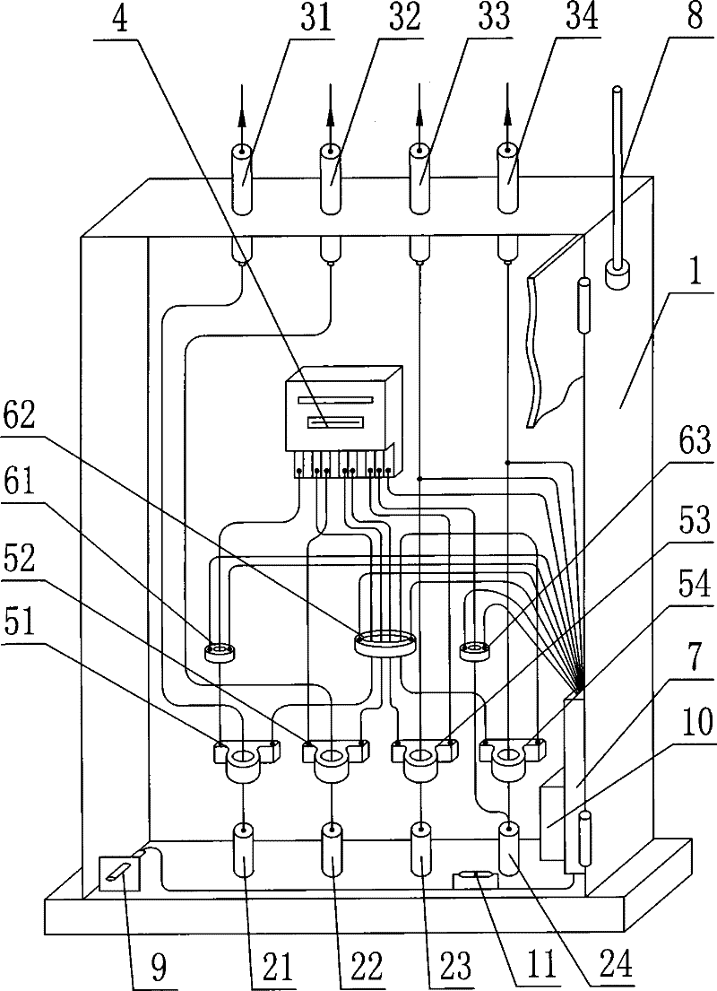
[0020] Such as figure 1 with figure 2As shown, the anti-stealing intelligent automatic management system includes a box body 1, and the input end of the box body 1 is provided with a first input ceramic terminal block 21, a second input ceramic terminal block 22, and a second input ceramic terminal block connected to the output line end of the transformer. Three-input ceramic terminal block 23, the fourth input cerami...


PUM


Abstract

The invention discloses an intelligent automatic management system for prevention of power theft. The system comprises a box; an input terminal of the box is provided with a first input ceramic connector base, a second input ceramic connector base, a third input ceramic connector base and a fourth input ceramic connector base, wherein the four input ceramic connector bases are connected with an output line terminal of transformer; and an output terminal of the box is provided with a first output ceramic connector base, a second output ceramic connector base, a third output ceramic connector base and a fourth output ceramic connector base; besides, an electric power gauge table is arranged in the box. Moreover, the system also includes a terminal information acquisition device, an information processing device, a signal sending and receiving device, a remote control platform and a terminal control device. According to the invention, power theft behaviors including a change of system wiring like circuit breakage, current division, and commutation and the like can be prevented; furthermore, a power theft behavior on a zero line under pressure can be monitored and prevented; and meanwhile, a remote real-time monitoring function can be realized; and the operation of the system is simple, practical, and reliable; therefore, great convenience is brought to work of an electric system; and safety of national electric power property is protected and illegal theft can be prevented.

Description

technical field [0001] The invention relates to a device for a power supply department to provide electric energy to users, in particular to an anti-stealing electricity management system for the power supply device. Background technique [0002] At present, in the process of measuring three-phase electricity users, the power supply company department cannot directly measure due to the large current used. Generally speaking, AC transformers are used to measure with electric energy meters. However, in this kind of measurement, the system wiring is changed, such as current circuit breaker, shunt, commutation, phase change, transformer reverse current reverse meter, phase line and neutral line interchange, voltage line open phase, phase change, and zero line with voltage Even cutting off the metering system and other means to steal electricity is sometimes difficult for the power department to find and find. The metering anti-stealing system adopted by the existing power suppl...

Claims


Application Information

Patent Timeline
Patent Type & Authority Applications(China)
IPC IPC(8): G01R11/24G01R11/04
Inventor 于波涛戚昌彬崔荣波杨立强
Owner 于波涛
Learn More