
Current reference generation circuit, constant current switch power supply control circuit and control method thereof

A generation circuit and current reference technology, applied in the direction of electric lamp circuit layout, electric light source, control/regulation system, etc., can solve the problems of sharp increase of input power, lack of AC input signal, etc., achieve high power factor, eliminate error, improve constant The effect of stream precision

Active Publication Date: 2013-11-27
HANGZHOU SILAN MICROELECTRONICS
View PDF3 Cites 0 Cited by
  • Summary
  • Abstract
  • Description
  • Claims
  • Application Information

AI Technical Summary

Problems solved by technology

However, in the presence of a phase-controlled dimmer, the AC input signal will be missing when the dimming angle is different, and its rectification is no longer a complete half-wave, so the input feedforward signal Vff contains the phase-cut angle signal, The voltage feed-forward control will cause Iref to increase sharply with the increase of the phase-cut angle, and the input power will also increase sharply, so the above method is not suitable for the occasion of phase-controlled dimming

Method used


Image

  • Current reference generation circuit, constant current switch power supply control circuit and control method thereof
  • Current reference generation circuit, constant current switch power supply control circuit and control method thereof
  • Current reference generation circuit, constant current switch power supply control circuit and control method thereof

Examples


Embodiment Construction

[0061] The content of the present invention will be described in detail below in conjunction with the block diagram of the present invention and the schematic diagrams of specific embodiments.

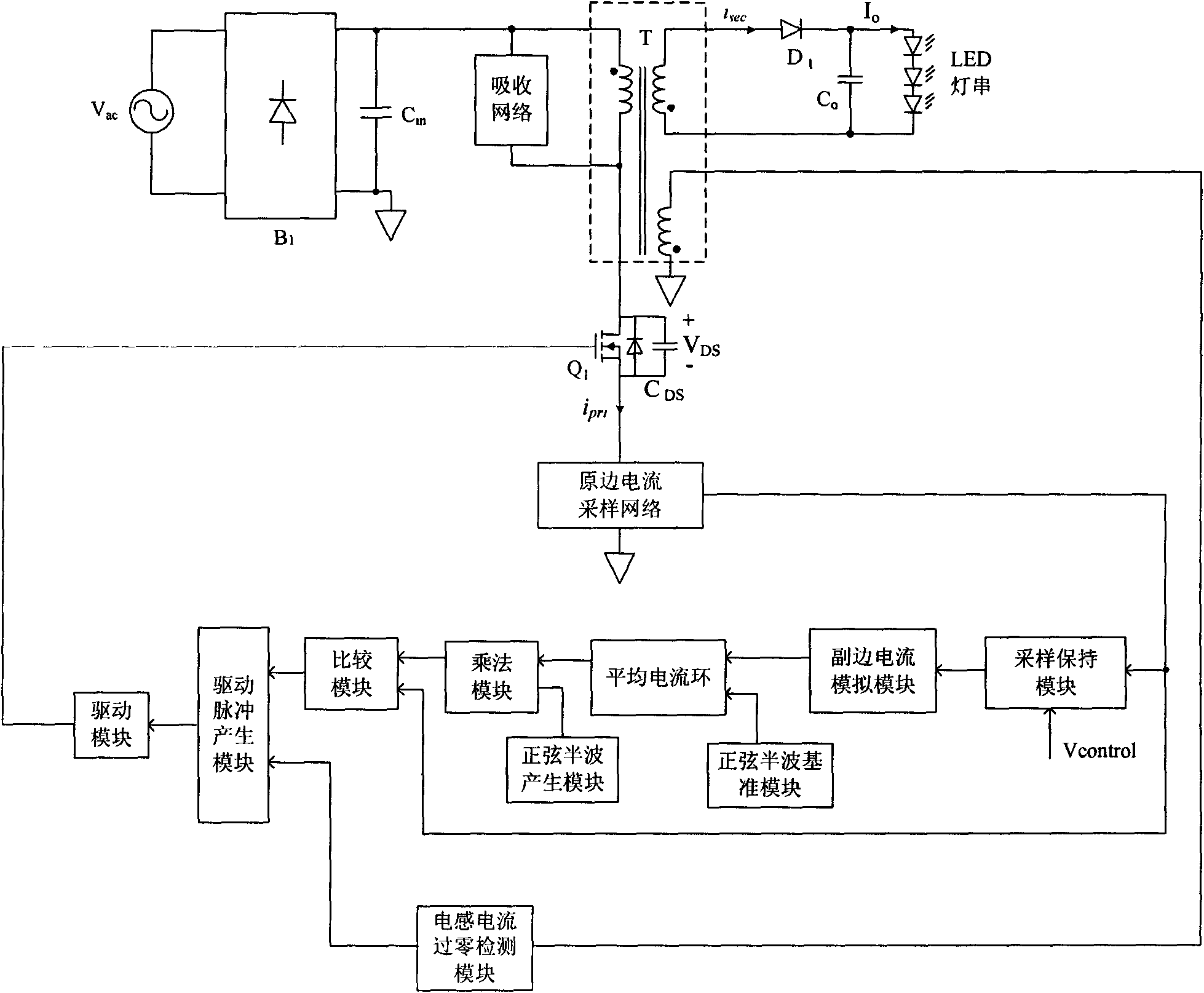
[0062] Such as Figure 6A As shown, the current reference generation circuit 100 of the present invention includes:

[0063] The first multiplier module 101: the first multiplier module 101 receives the rectified voltage waveform signal Iac output from the rectifier bridge of the switching power supply main circuit and the error amplification signal Vcomp output by the average current loop 104, and generates a half-sine wave signal Iref, The sine half-wave signal Iref has the same frequency and phase as the rectified voltage waveform signal Iac, the amplitude of the sine half-wave signal Iref changes with the error amplification signal Vcomp, and the sine half-wave signal Iref is used as the primary current signal of the switching power supply main circuit to follow base signal;

[0...


PUM


Abstract

A current reference generating circuit including a first multiplier module, configured to receive a rectified voltage waveform signal of a switch mode power supply and an output signal generated by an average current loop, and to generate a sinusoidal half-wave signal having the same frequency and phase as the rectified voltage waveform signal, the sinusoidal half-wave signal varies with the output signal generated by the average current loop. A second multiplier module, configured to receive the sinusoidal half-wave signal and a control signal to generate a pulse signal. An average current loop for comparing the average of the pulse signal to a predetermined average current loop reference signal. The circuit can generate a self-adapted reference signal that follows the primary-side current signal of main circuit of the switch mode power supply, which is then supplied to the constant current switch mode power supply control circuit with high power factor.

Description

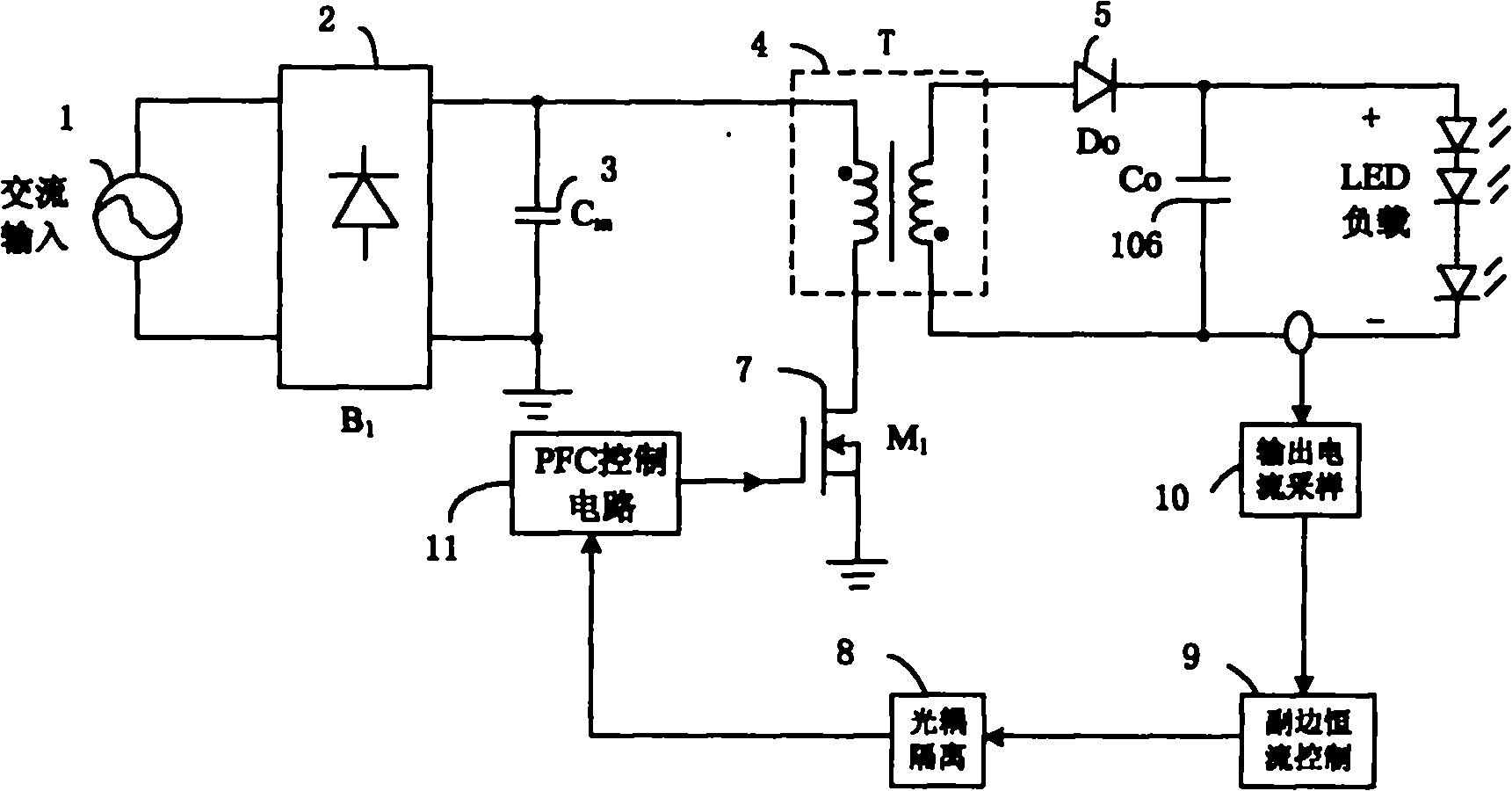
technical field [0001] The invention belongs to the technical field of switching power supplies, and relates to a high power factor constant current switching power supply primary side current reference generation circuit, control circuit and method for adaptive primary side control. Background technique [0002] At present, many isolated power supplies such as mobile phone chargers and high-power LED drivers usually require the circuit to have the function of outputting constant current due to application requirements; IEC1000-3-2, etc., the above isolated power supply must also have power factor correction (PFC) function, figure 1 It is a commonly used single-stage power factor correction scheme at present: by detecting the output current on the secondary side of the transformer, after the secondary side is controlled by constant current, it is fed back to the primary side PFC control circuit through the optocoupler. figure 1 In the prior art solution shown, due to the ex...

Claims


Application Information

Patent Timeline
Patent Type & Authority Patents(China)
IPC IPC(8): H02M3/335H02M1/42H05B37/02
CPCY02B70/126H02M1/4258H05B45/382H05B45/355Y02B70/10H05B45/385H05B45/3725
Inventor 谢小高吴建兴
Owner HANGZHOU SILAN MICROELECTRONICS
Learn More