
A sample low temperature automatic storage device and method

A technology for low-temperature storage and storage equipment, which is applied to the field of low-temperature automatic storage equipment for samples, and can solve the problems of complex structure, low efficiency of manual sample storage and sample storage, and reduced sample testing timeliness.

Active Publication Date: 2021-06-04
DIRUI MEDICAL TECH CO LTD
View PDF0 Cites 0 Cited by
  • Summary
  • Abstract
  • Description
  • Claims
  • Application Information

AI Technical Summary

Problems solved by technology

[0004] The existing low-temperature storage equipment can be divided into two types: one is the low-temperature storage equipment for samples that are manually taken and placed. The efficiency of manually taking and placing samples to store samples is low, and when samples are re-tested, errors in identifying samples are prone to occur, resulting in time-limited sample testing. Reduction of stability, so automatic cryogenic storage equipment appeared
[0005] The second is the automatic low-temperature storage device used on the automatic detection assembly line. This type of automatic low-temperature storage device is usually divided into two structural forms. One is that the device is designed with multiple manipulators for taking and placing samples, or a multi-degree-of-freedom machine. The structure of this structure is complex, but the space utilization rate is high and the number of samples stored is large. The other structure is that there is no pick-and-place manipulator in the storage device, but the internal sample storage position is in a linked state. When a certain sample is to be taken , the samples in the low-temperature storage device need to follow the movement, which increases the risk of sample damage and positioning error. When the mechanism fails, the maintenance is complicated and the maintenance time is increased.

Method used


Image

  • A sample low temperature automatic storage device and method
  • A sample low temperature automatic storage device and method
  • A sample low temperature automatic storage device and method

Examples


Embodiment

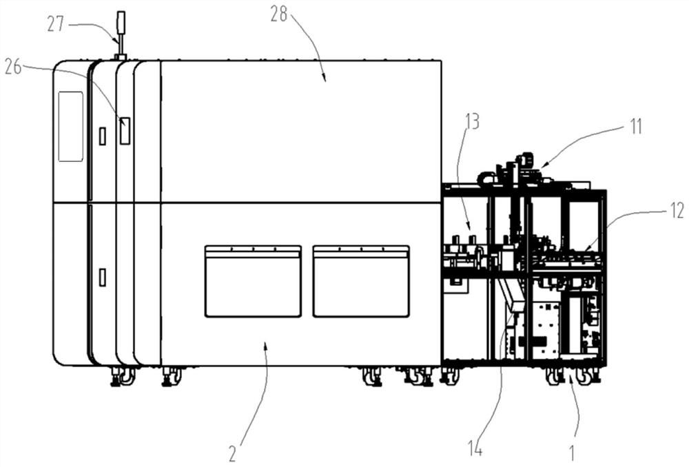
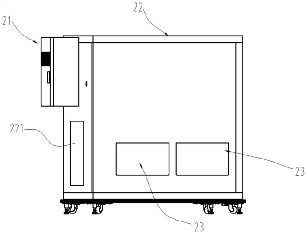
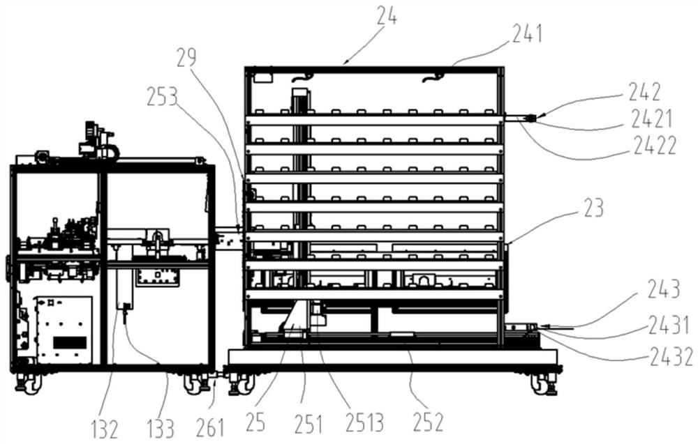
[0075] Embodiment: a kind of sample cryogenic automatic storage equipment, such as Figure 1 to Figure 4 As shown, it includes a sample collection module 1, a low temperature storage module 2, a sample rack 4 and a control system.

[0076] The sample collection module 1 is used to collect samples that need to enter the low-temperature storage module 2 on the automatic inspection line, and load the samples in the low-temperature storage module 2 to the automatic inspection line. Wherein, the sample collection module 1 in the present invention mainly provides the function of a sample entry and exit interface.

[0077] The low-temperature storage module 2 is arranged at one end of the sample collection module 1, and the low-temperature storage module 2 is used to provide a low-temperature stable storage environment for the samples, and dispatches the sample racks 4 according to the instructions of the control system.

[0078] The sample rack 4 is disposed between the sample coll...


PUM


Abstract

The invention discloses a sample low-temperature automatic storage device and method. The device includes: a sample collection module, a low-temperature storage module, a sample rack and a control system; the sample collection module is used to collect samples that need to enter the low-temperature storage module on an automatic inspection assembly line, And, load the samples in the low-temperature storage module to the automatic inspection line; the low-temperature storage module is set at one end of the sample collection module, and the low-temperature storage module is used to provide a low-temperature stable storage environment for the samples, and transport the sample racks according to the instructions of the control system ;The sample rack is used to store and transport samples; the control system is electrically connected to the sample collection module, the low-temperature storage module and the sample rack; to achieve automatic sample collection, transfer, and low-temperature storage of samples, as well as automatic discarding of samples and manual Bulk discarding purposes.

Description

technical field [0001] The present invention relates to a kind of automation equipment of laboratory department of hospital, more specifically, it relates to a kind of low-temperature automatic storage equipment and method of samples. Background technique [0002] The so-called "sample" refers to the biological material collected by the hospital from the patient for medical testing. Generally, after relevant medical testing is carried out on the sample, the test result needs to be evaluated and confirmed by a doctor or the instrument test takes a long time. At this time, the sample needs to be stored at low temperature. Storage in equipment to prevent corruption of samples. [0003] The low-temperature automatic storage system for samples is used in the post-processing of the automatic detection pipeline in the laboratory department of the hospital. The samples that have completed relevant medical tests are automatically entered into the low-temperature automatic storage sys...

Claims


Application Information

Patent Timeline
Patent Type & Authority Patents(China)
IPC IPC(8): F25D11/00F25D23/12F25D25/04F25D25/02F25D23/02F25D29/00
CPCF25D11/00F25D23/02F25D23/12F25D25/02F25D25/04F25D29/003
Inventor 狄英杰刘展宏白晓亮
Owner DIRUI MEDICAL TECH CO LTD
Learn More