
Ultrasound probe

An ultrasonic and imaging probe technology, applied in the field of ultrasonic probes, can solve the problems of not supporting multi-dimensional imaging applications, inability to use multi-dimensional imaging, lack of appropriate circuits, etc.

Inactive Publication Date: 2012-03-07
BK MEDICAL HLDG CO INC
View PDF6 Cites 10 Cited by
  • Summary
  • Abstract
  • Description
  • Claims
  • Application Information

AI Technical Summary

Problems solved by technology

[0006] Unfortunately, some ultrasound probes can only be controlled by the ultrasound imaging system and are configured so that they only work with specific ultrasound imaging systems
As a result, probes configured for multidimensional imaging may not be usable for multidimensional imaging when used with ultrasound imaging systems that do not support multidimensional imaging applications
Additionally, probes constructed with specific interfaces may not work with consoles that do not have complementary interfaces
Also, the console may lack the proper circuitry to control the various components of the probe it communicates with

Method used


Image

  • Ultrasound probe
  • Ultrasound probe
  • Ultrasound probe

Examples


Embodiment Construction

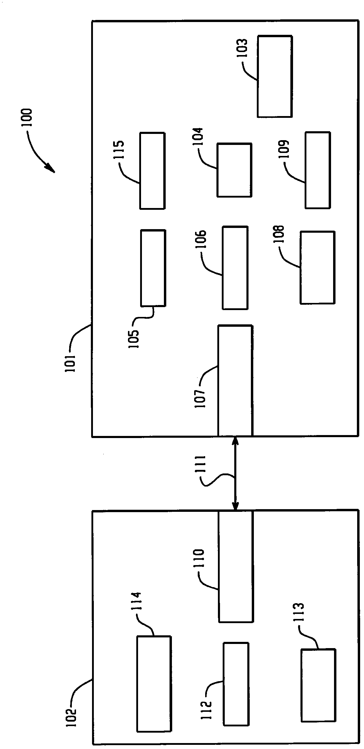
[0021] figure 1 An ultrasound imaging system 100 including a probe 101 and a console 102 is depicted. Probe 101 is capable of multi-dimensional applications, such as two-, three-, and four-dimensional applications, and includes a movable transducer array 103 having one or more transducer elements that transmit and detect signals. Non-limiting examples of suitable transducer elements include piezoelectric elements, MEMS elements, and / or other transducer elements.

[0022] Electromechanical drive system 104 moves and / or orients movable transducer array 103 via motor 115 . In one example, this includes converting rotation of the motor 115 into translational, rotational and / or oscillating motion of the ultrasound transducer array 103 . Suitable motors 115 may include, but are not limited to, stepper motors, DC motors, ultrasonic motors, piezoelectric motors, electromagnetic motors, and / or other motors. The illustrated drive system 104 and motor 115 are configured to alternately...


PUM


Abstract

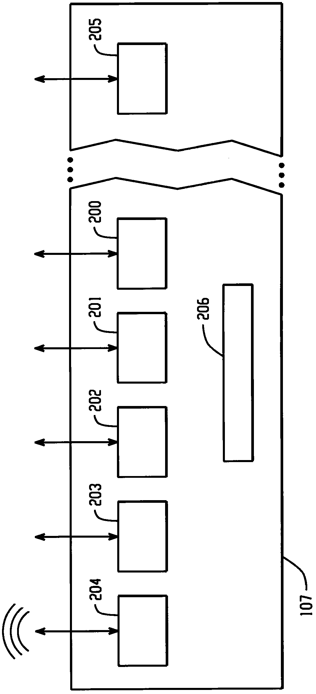
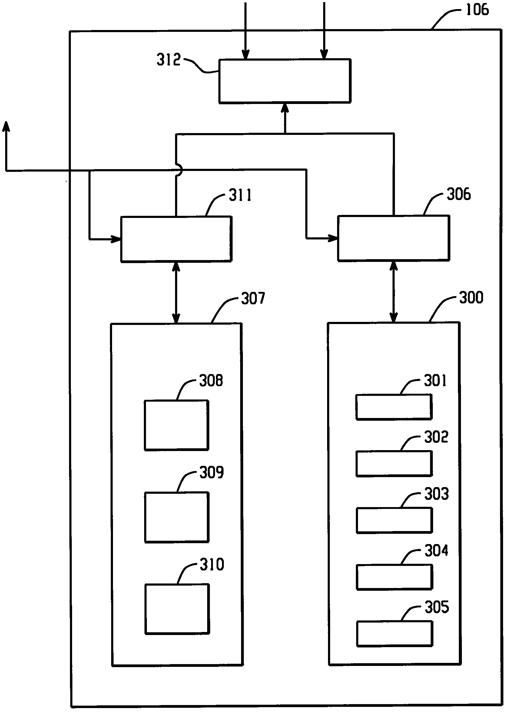
An ultrasound imaging probe (101) includes a communications interface (107), including one or more ports (200-205), corresponding to one or more different communication protocols, for communication with ultrasound consoles. The probe (101) also includes a controller (106) that configures the probe (101) for communication with an ultrasound console (102) over a port (200-205) based on a communication between the communications interface (107) and a communications interface (110) of the console (102).

Description

[0001] Cross References to Related Applications [0002] This application claims the benefit of priority to Provisional Patent Application Serial No. 61 / 165,630, Acknowledgment Code 4363, filed April 1, 2009, and entitled "Ultrasonic Probe," which is incorporated by reference in its entirety here. technical field [0003] The following generally relates to ultrasound probes, and more particularly to ultrasound probes configured for multi-dimensional imaging. Background technique [0004] Ultrasound imaging probes generally include one or more transducer arrays affixed to the distal end of a mechanical device or handle, and can be used for imaging of anatomical structures or organs. Volumetric imaging can be performed by utilizing a two-dimensional transducer array within the probe with no moving parts, or by electromechanically moving a one-dimensional transducer array within the probe. Volumetric imaging has been used to visualize 3D structures in the human body, such as ...

Claims


Application Information

Patent Timeline
Patent Type & Authority Applications(China)
IPC IPC(8): A61B8/00
CPCA61B8/00A61B8/12A61B8/4254A61B8/4455A61B8/4461A61B8/4472A61B8/4477A61B8/4488A61B8/467A61B8/483A61B8/546
Inventor A·古比尼W·R·德雷谢尔
Owner BK MEDICAL HLDG CO INC
Learn More