Surface treatment device

A surface treatment device and a technology for processing objects, which are applied to the used abrasive treatment device, abrasive feeding device, abrasive and other directions, can solve the problems of projectile scattering and leakage, and achieve the prevention or inhibition of projectiles, prevention or inhibition device The effect of endoleak

Active Publication Date: 2012-03-14
SINTOKOGIO LTD
View PDF9 Cites 4 Cited by
  • Summary
  • Abstract
  • Description
  • Claims
  • Application Information

AI Technical Summary

Problems solved by technology

[0003] However, in this device, projectiles, etc. may scatter and leak out of the device.

Method used


Image

  • Surface treatment device
  • Surface treatment device
  • Surface treatment device

Examples


no. 1 Embodiment approach

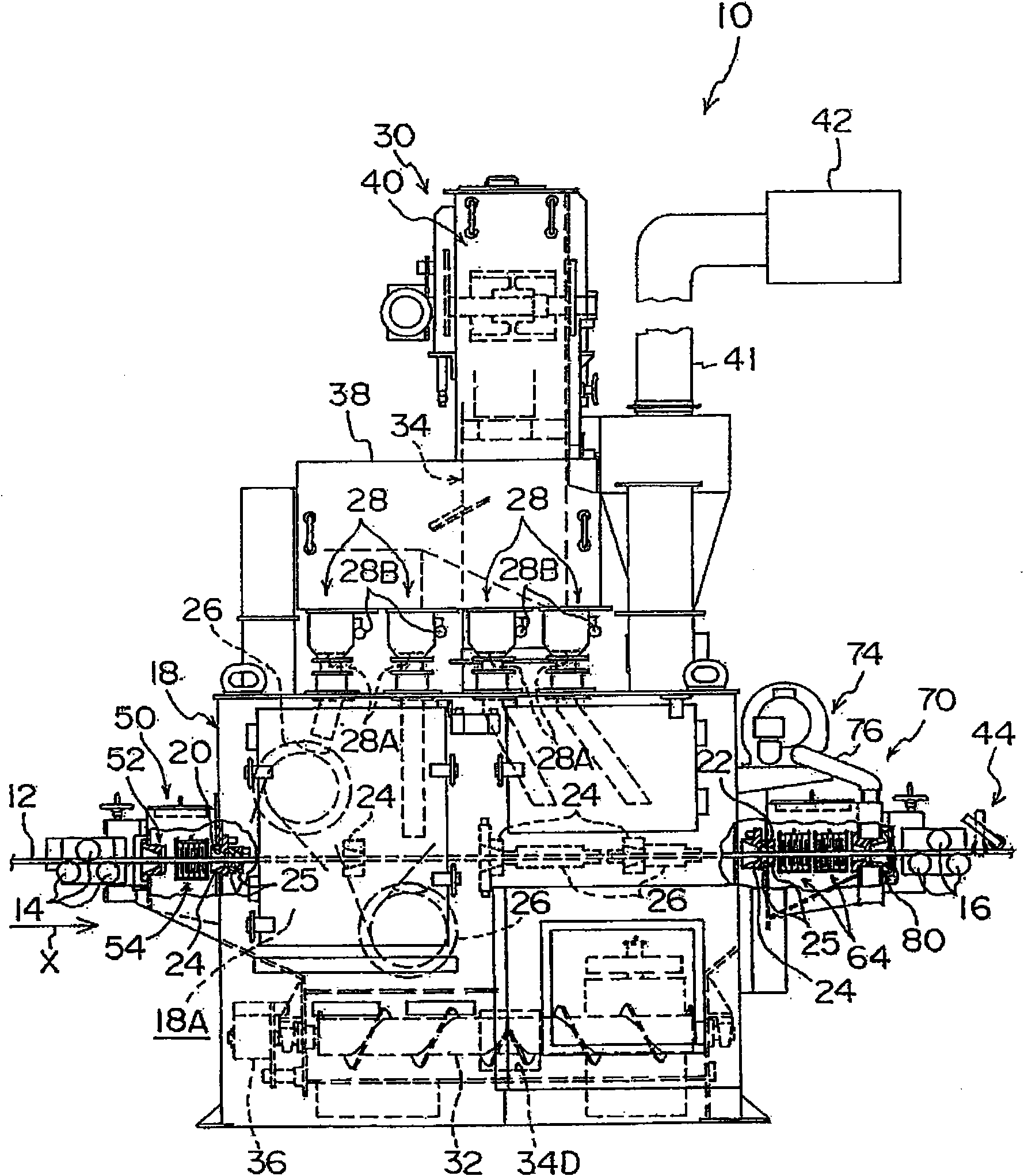
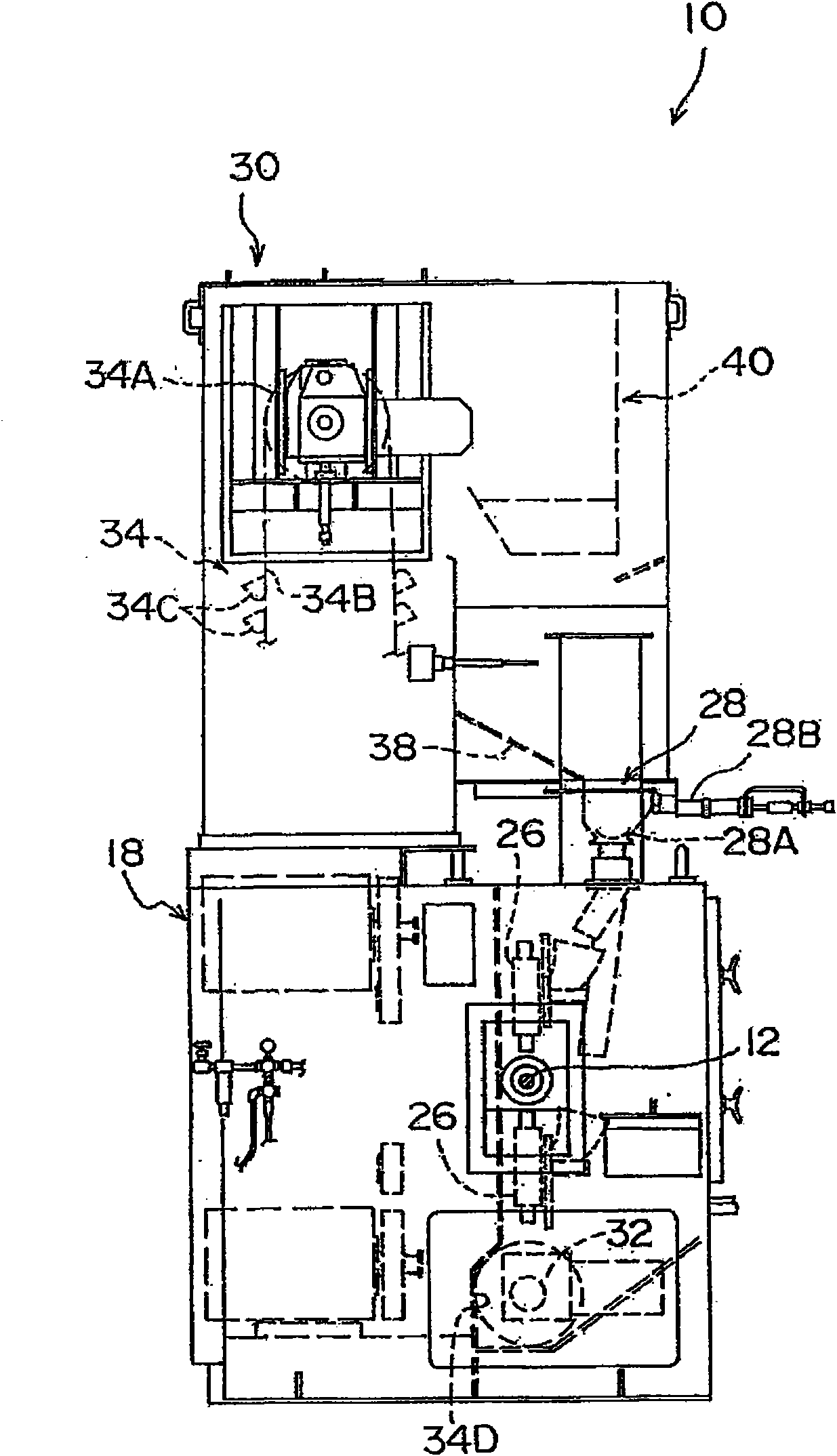
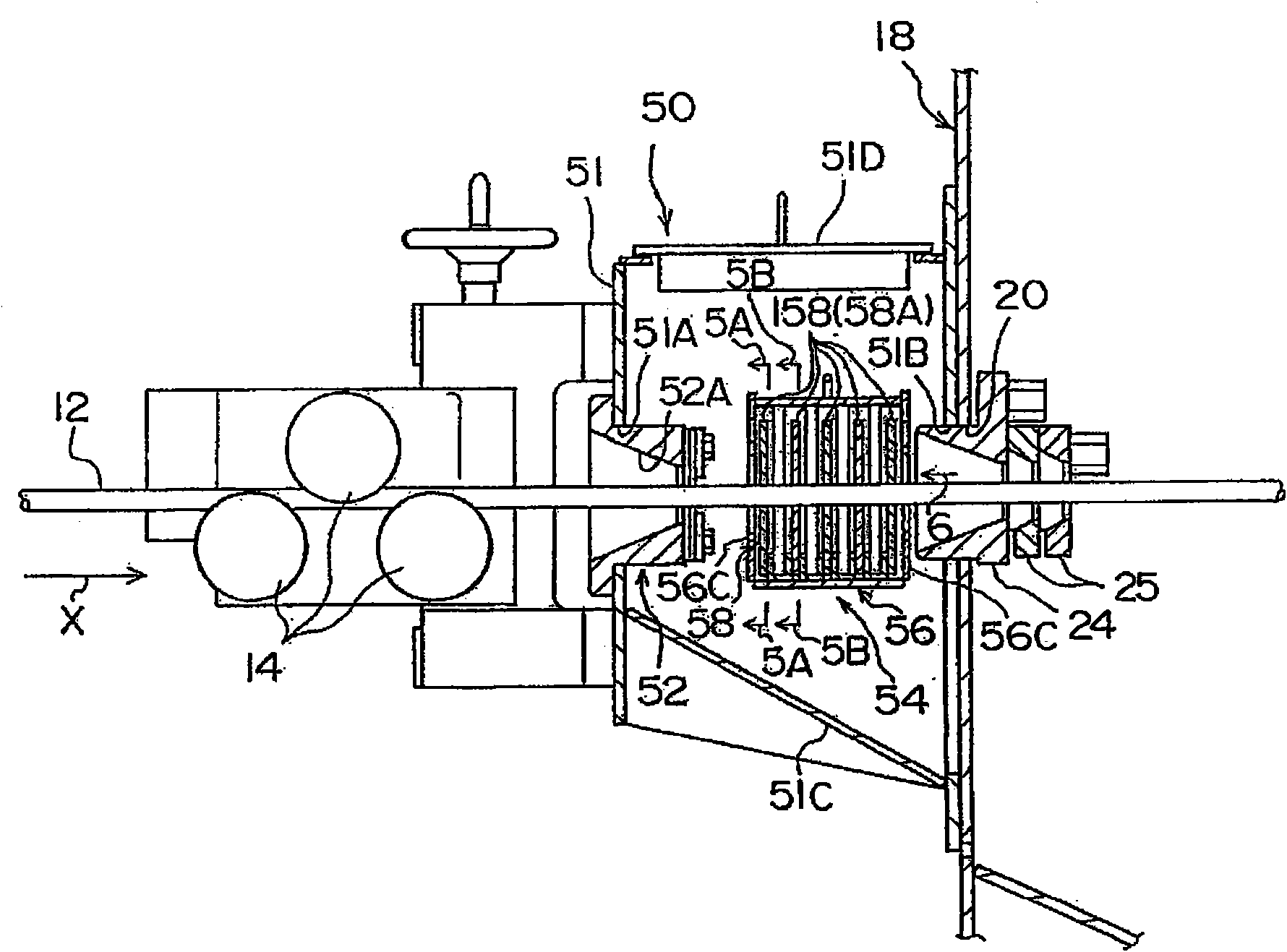
[0048] use Figure 1 to Figure 7 The shot blasting apparatus which is the surface treatment apparatus which concerns on 1st Embodiment of this invention is demonstrated. figure 1 The shot blasting device 10 is shown in a front view, figure 2 The shot blasting device 10 is shown in left side view.

[0049] In addition, in the shot blasting apparatus 10 which concerns on this embodiment, the metal wire rod 12 is made into the object to be processed. Arrow X indicated in the figure shows the conveyance direction of the conveyance wire 12 (hereinafter referred to as "wire conveyance direction").

[0050] in relation to figure 1 A wire supply device (not shown) is arranged on the upstream side (left side in the figure) in the wire feeding direction (wire traveling direction) of the shown shot blasting device 10 . The wire supply device is used to supply the wire 12 to the shot blasting device 10, and includes: an unwinding part for winding the wire 12 before the shot blasting ...

no. 2 Embodiment approach

[0088] Next, use Figure 8 Figure 10 The shot blasting apparatus of the surface treatment apparatus which concerns on 2nd Embodiment of this invention is demonstrated. Figure 8 In the front view, the shot blasting apparatus 90 which concerns on the 2nd Embodiment of this invention is shown, Figure 9 The shot blasting device 90 is shown in a left side view, Figure 10 The shot blasting device 90 is shown in right side view. As shown in the above-mentioned figure, in the shot blasting device 90, the same as the shot blasting device 10 related to the first embodiment (refer to figure 1 ) The difference is to replace the screw conveyor 32 (refer to figure 1 ), and an inclined portion 92 is formed at the bottom of the chamber 18 . Other configurations are basically the same as those of the first embodiment. In this way, the same reference numerals are assigned to components substantially the same as those in the first embodiment, and description thereof will be omitted.

...


PUM


Abstract

In order to obtain a surface treatment device capable of preventing or suppressing the leakage of a projection material and the like from within the device, a first seal part (54) is disposed on the carry-in port (20) side of a cabinet (18), and a second seal part (64) is disposed on the carry-out port (22) side of the cabinet (18). A blowoff port (72) of an air current production unit (70) is disposed downstream from the second seal part (64) in a wire rod transfer direction, and the air current production unit (70) produces an air current directed toward the inside of the cabinet (18). Consequently, even if a projection material and the like remain on a wire rod (12), the projection material and the like are returned to the inside of the cabinet (18) by the air current.

Description

technical field [0001] The present invention relates to a surface treatment device for performing surface treatment by projecting projectiles on the surface of an object to be treated such as a wire rod. Background technique [0002] Among the surface treatment devices, for example, there is a device that loads wires and the like into a chamber and performs shot blasting by projecting projectiles on the surface of the loaded wires and the like (for example, refer to JP 2003-334759 A). [0003] However, in this device, bullets and the like may scatter and leak out of the device. Contents of the invention [0004] The present invention is made in view of the above circumstances, and an object of the present invention is to provide a surface treatment device capable of preventing or suppressing leakage of projectiles and the like from the device. [0005] The surface treatment device according to the first aspect of the present invention includes: a projectile device that pr...

Claims


Application Information

Patent Timeline
IPC IPC(8): B24C3/02B24C5/00B24C9/00
CPCB24C1/086B24C3/10B24C7/0046
Inventor 岩田恭一
Owner SINTOKOGIO LTD
Why Eureka
Try Eureka