Transposition device for electronic elements

An electronic component and indexing technology, which is applied in the direction of conveyor objects, transportation and packaging, etc., can solve the problems of reducing use efficiency and component life, increasing volume, occupying space, etc.

Active Publication Date: 2012-03-14
HON PRECISION INC
View PDF6 Cites 5 Cited by
  • Summary
  • Abstract
  • Description
  • Claims
  • Application Information

AI Technical Summary

Problems solved by technology

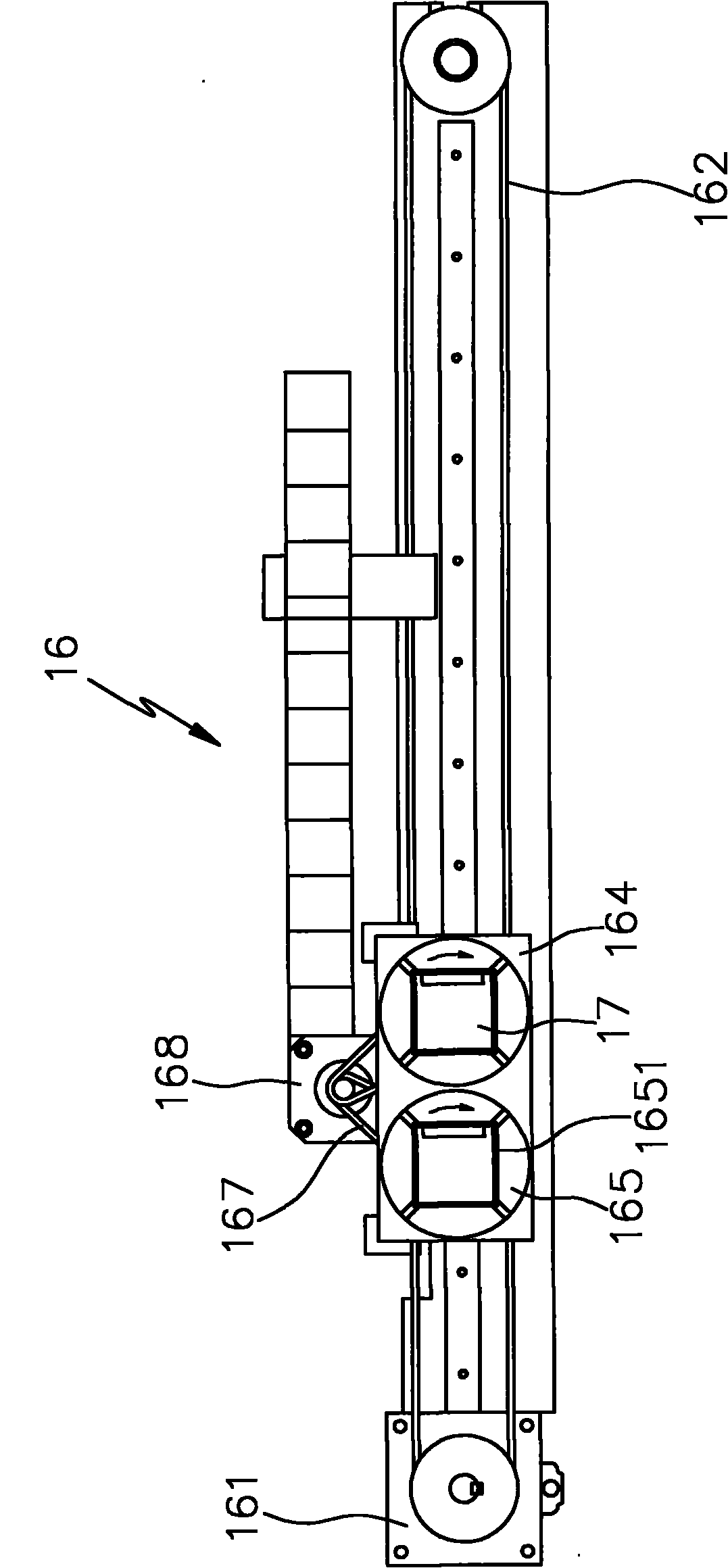
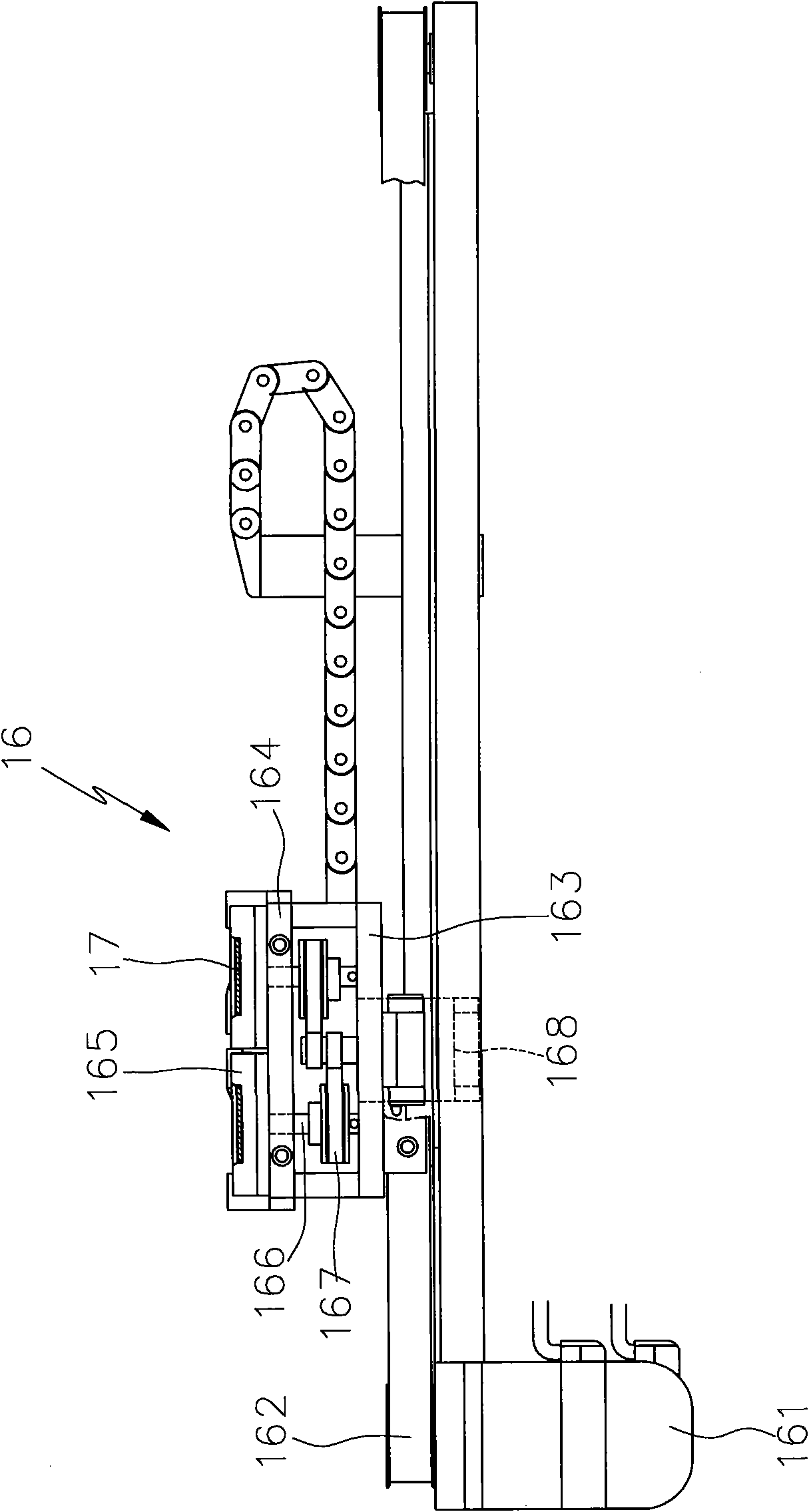
[0003] 1. The transfer mechanism 16 is additionally equipped with components such as two shaft rods 166, two pulley sets 167 and a motor 168 for indexing on the platen 163 to drive the rotation of the two bearing seats 165 so as to adjust the poles of the electronic components 17. Sexual direction, not only the assembly of components is cumbersome and time-consuming, but also increases the cost of equipment
[0004] 2. The transfer mechanism 16 drives the two pulley sets 167 and the two shafts 166 with the motor 168 for indexing, so that the electronic components 17 on the two bearing seats 165 can adjust the polarity direction. When there are two bearing seats 165, a whole set of indexing motors 168, two pulley sets 167, and two shaft rods 166 must be added, which not only makes it inconvenient to add bearing seats 166, but also increases the equipment cost.
[0005] 3. The transfer mechanism 16 is additionally equipped with components such as two shaft rods 166, two pulley sets 167 and a motor 168 for indexing on the platform 163 to adjust the polarity direction of the electronic components 17 on the two bearings 165, This will lead to an increase in the volume of the entire transfer mechanism 16, which takes up quite a lot of space, which is not conducive to the space configuration of the machine.
[0006] 4. Due to the quantity of the transfer mechanism 16 according to the bearing seat 165, at least one whole group of two shaft rods 166, two pulley sets 167 and the indexing motor 168 and other components are assembled on the platen 163, so that the number of the platen 163 is increased. Due to the heavy load, the motor 161 for displacement is very laborious in driving the displacement of the platen 163, and the displacement speed of the platen 163 is reduced, which increases the time for carrying and transporting, resulting in reduced use efficiency and loss of component life

Method used


Image

  • Transposition device for electronic elements
  • Transposition device for electronic elements
  • Transposition device for electronic elements

Examples


Embodiment Construction

[0034] In order to enable your examiner to have a further understanding of the present invention, hereby cite a preferred embodiment together with the accompanying drawings, and describe it in detail as follows:

[0035] see Figure 4 , Figure 5 , Figure 6 and Figure 7, the indexing device 20 of the present invention is assembled on the machine platform, and includes an organic base 21, a bearing seat 22, a cover 23 and a sliding member 24, and the base 21 is provided with a plurality of positioning pins 211 and concave holes 212 on the top surface, Each positioning pin 211 is used to guide the pick-and-place device of the material transfer device (not shown) in alignment, so that the pick-and-place device can accurately pick and place electronic components, and the bottom surface of each concave hole 212 is equipped with a bearing 213. The bottom surface of the base 21 is provided with at least one chute 214, and the chute 214 is communicated with each concave hole 212....


PUM


Abstract

The invention relates to a transposition device for electronic elements. The transposition device is arranged on a machine platform and is provided with a machine base which can be assembled on a movable or fixed platen; the machine base is provided with at least one concave hole on a top surface and is provided with a sliding chute which is communicated with each concave hole on a bottom surface, and a bearing base with an accommodating groove is arranged in each concave hole to bear the electronic elements; the bottom surface of each bearing base is connected with a rotary platform with a guide pin; a sliding piece which is arranged in the sliding chute of the machine base in a sliding mode is provided with guide grooves at the corresponding positions of the guide pins of the bearing bases, so that the guide pins are inserted into the guide grooves; and a driving source is arranged on the lateral side of the sliding piece to drive the sliding piece to make horizontal displacement, so that the guide groove of the sliding piece pushes the guide pin of each bearing base to swing, and the bearing base rotates to adjust the polar direction of the electronic elements on each bearing base synchronously. Therefore the electronic elements can be transferred by utilizing connecting rod type transmission design to reduce the elements substantially and arrange the bear bases additionally and easily, and the practical benefit of saving cost and improving production efficiency is achieved.

Description

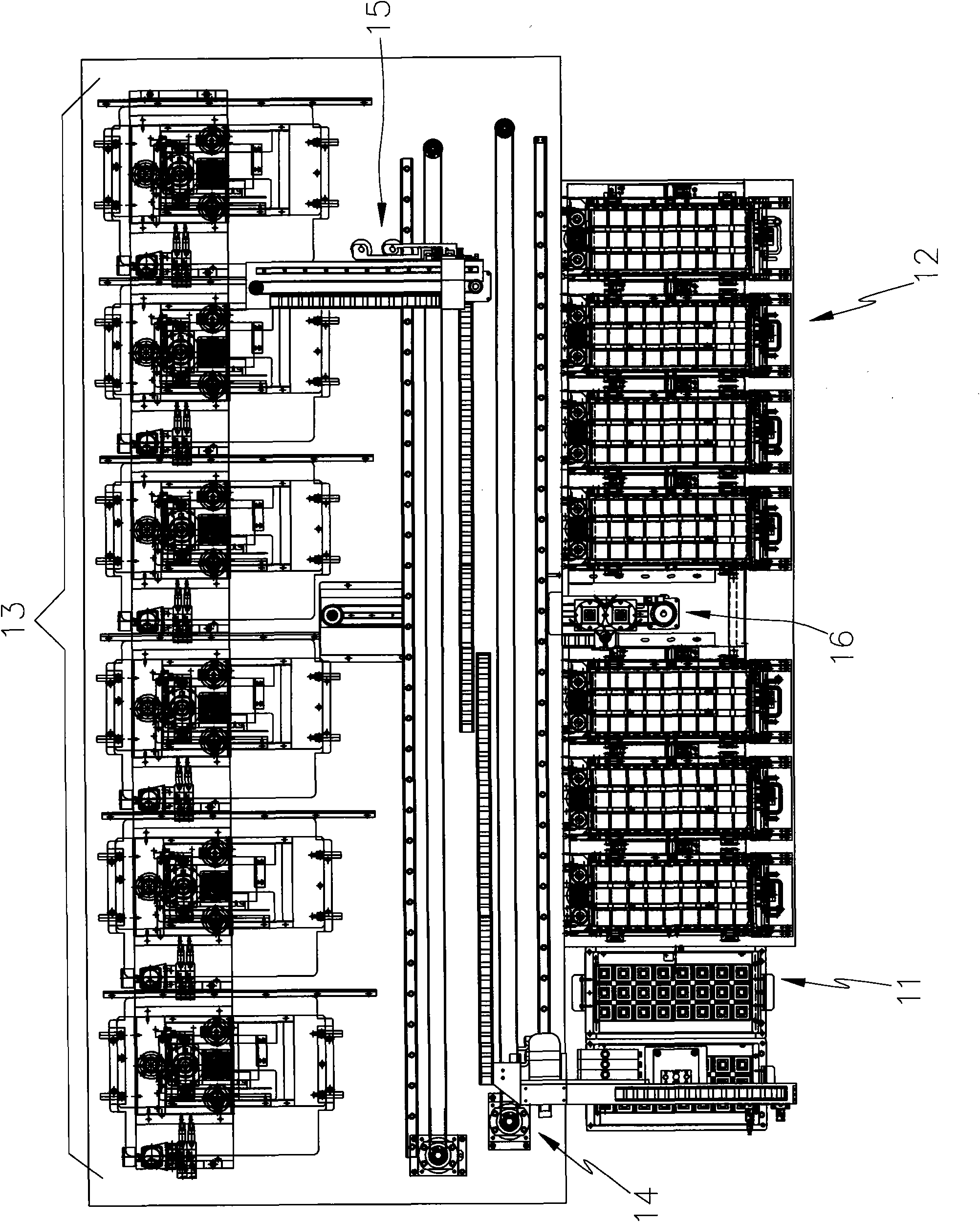
technical field [0001] The invention relates to an indexing device which can greatly reduce the number of transmission elements, and is easy to add seats, thereby saving costs and improving production efficiency. Background technique [0002] see figure 1 , for the applicant’s previous application for the Taiwan Invention No. 91210786 "Transportation device for IC testing machine" patent case, which is equipped with a feeding box 11, a receiving box 12, a testing platform 13, and a left cantilever pick-and-place mechanism on the machine 14 and the right cantilever pick-and-place mechanism 15 are also provided with a transfer mechanism 16 that can move back and forth between the supply and receiving boxes 11, 12 and the detection platform 13, in order to transfer the electronic components to be tested / finished. The polarity direction of the electronic components to be tested in the box 11 is different from the polarity direction of the test socket of the detection station 13...

Claims


Application Information

Patent Timeline
Patent Type & Authority Applications(China)
IPC IPC(8): B65G47/74B65G47/24
Inventor 谢旼达
Owner HON PRECISION INC
Why Eureka
Try Eureka