
Light conductor

A technology of light guide body and light guide part, which is applied in the field of light guide body to achieve the effect of increasing beautiful design, saving production cost and assembly man-hours, and increasing the light output angle

Inactive Publication Date: 2012-03-14
AMA PRECISION INC
View PDF3 Cites 4 Cited by
  • Summary
  • Abstract
  • Description
  • Claims
  • Application Information

AI Technical Summary

Problems solved by technology

In the prior art, limited to the position where the LED is fixed by the package, the light source generated by it can only emit light at 180 degrees forward, that is, it can only be scattered in the upper half of the space where it is fixed, unlike traditional tungsten lamps or fluorescent lamps Can glow around the center

Method used


Image

  • Light conductor
  • Light conductor
  • Light conductor

Examples


Embodiment Construction

[0020] A light guide according to a preferred embodiment of the present invention will be described below with reference to related drawings, wherein the same elements will be described with the same reference symbols.

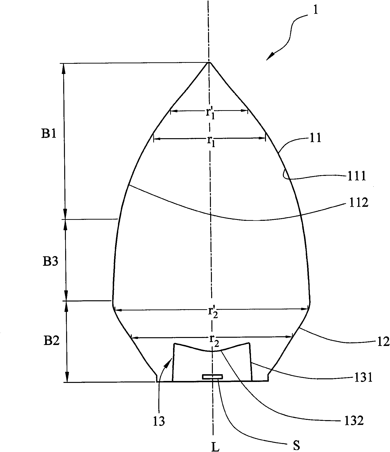
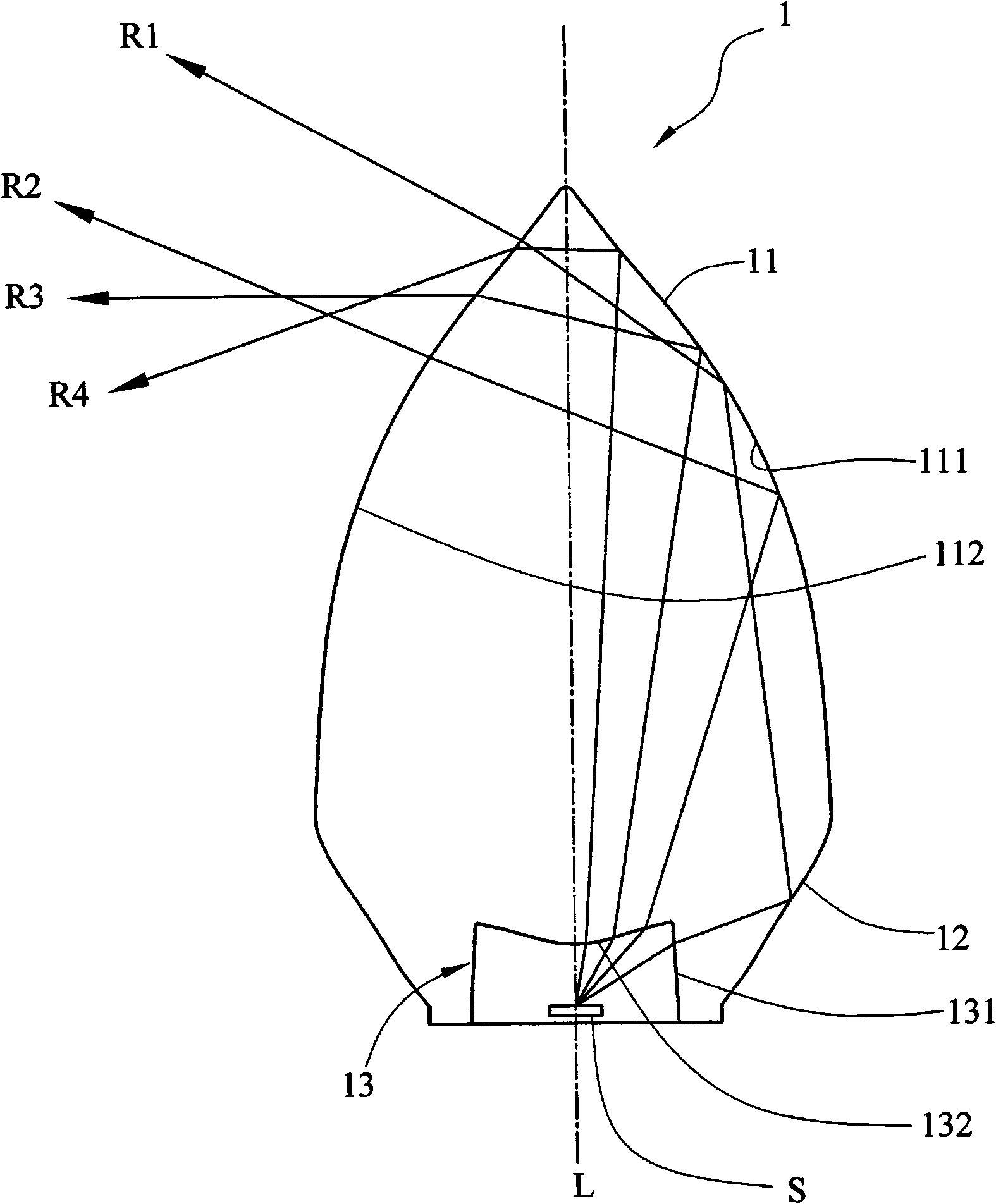
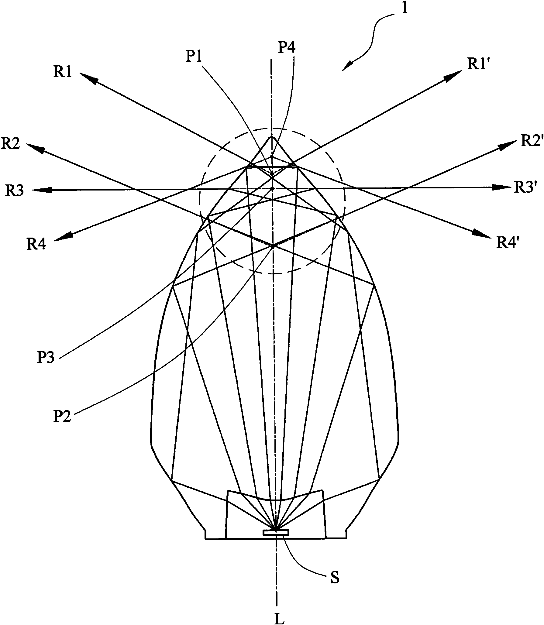
[0021] Please also refer to Figure 1A and 1B shown, where Figure 1A is a cross-sectional view of a light guide in a preferred embodiment of the present invention, and Figure 1B for Figure 1A A schematic diagram of part of the light path within the light guide shown. Such as Figure 1A As shown, in this embodiment, the light guide 1 is applied to a light-emitting diode S. Of course, the type and luminous intensity of the light-emitting diode S are not particularly limited, and the color of the light source of the light-emitting diode S can be selected arbitrarily according to requirements, and can be matched with different The circuit design of the light emitting diode S produces different frequencies (blinking speed) or different brightness levels, and th...


PUM


Abstract

The invention relates to a light conductor, which is applied to a luminous diode, and comprises a lower light guiding part and an upper light emitting part. One end of the lower light guiding part receives optical lines transmitted by the luminous diode. The upper light emitting part is the other end of the lower light guiding part to be opposite to the luminous diode, and the upper light emitting part is provided with a first curved surface and a central axis. The first curved surface surrounds the central axis, and the radius of the first curved surface is gradually reduced along the direction that the central axis is away from the luminous diode. The optical lines are guided by the lower light guiding part to the upper light emitting part, then the optical lines are reflected by the first curved surface from one side of the central axis inside the upper light emitting part to the other side of the central axis, and finally the optical lines are is transmitted out of the upper light emitting part from the first curved surface at the other side of the central axis. Compared with the prior art, by adopting the particular upper light emitting part, the light conductor can take into account both the function and the shape and can substitute a function of a candle without adding an outer transparent glass cover under the situation that a situational application is required, so the production cost and the assembling work hours can be effectively reduced.

Description

technical field [0001] The present invention relates to a light guide, in particular to a light guide for light-emitting diodes. Background technique [0002] In order to provide users with different situational light sources, in addition to making different choices in the design of the light source, common ones such as tungsten lamps, fluorescent lamps, or light-emitting diodes, etc., are also equipped with different lampshade designs on the outside of the light source. Patterns or color matching produce a variety of situational light sources. [0003] As the luminous efficiency of light-emitting diodes is getting higher and higher, generally speaking, they are gradually replacing traditional tungsten lamps or fluorescent lamps. In the prior art, limited to the position where the LED is fixed by the package, the light source generated by it can only emit light at 180 degrees forward, that is, it can only be scattered in the upper half of the space where it is fixed, unlike...

Claims


Application Information

Patent Timeline
Patent Type & Authority Applications(China)
IPC IPC(8): F21V8/00F21Y101/02
Inventor 梁峻玮
Owner AMA PRECISION INC
Learn More