
Method for interacting by adopting optical indicator, optical indicator as well as presentation method and system

An indicator and optical technology, applied in the field of using optical indicators to interact with equipment, optical indicators, can solve the problems of low detection speed and reliability, difficult implementation, and increased detection difficulty, so as to improve detection accuracy and Reliability, ease of use, and simple effect detection

Inactive Publication Date: 2012-03-14
SHARP KK
View PDF1 Cites 8 Cited by
  • Summary
  • Abstract
  • Description
  • Claims
  • Application Information

AI Technical Summary

Problems solved by technology

[0007] (1) It is necessary to generate some characteristics of the optical indicator, such as shape, color, brightness, etc., but the generation of these characteristics is relatively difficult;
[0008] (2) It is necessary to detect these characteristics of the optical pointer, but the realization of this detection is difficult, especially in the case of images on the screen
In addition, some characteristics, such as shape, may change with the position of the optical indicator, which increases the difficulty of detection;
[0009] (3) Detection speed and reliability are low;
[0010] (4) The number of interactive events that can be represented is limited

Method used


Image

  • Method for interacting by adopting optical indicator, optical indicator as well as presentation method and system
  • Method for interacting by adopting optical indicator, optical indicator as well as presentation method and system
  • Method for interacting by adopting optical indicator, optical indicator as well as presentation method and system

Examples


Embodiment Construction

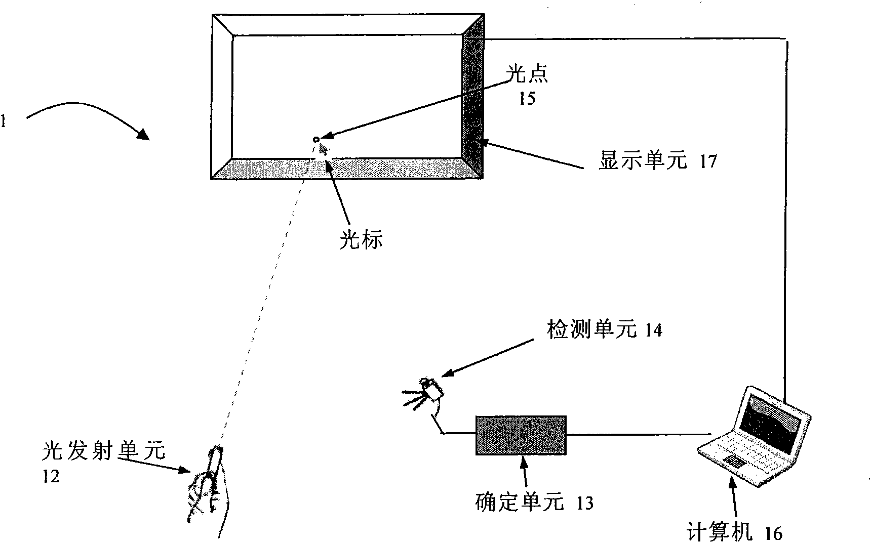
[0057] Exemplary embodiments of the present invention will be described in detail below with reference to the accompanying drawings, but the embodiments of the present invention are not limited to the following exemplary embodiments. In order to clearly describe the basic idea of ​​the present invention, only the components, functions or steps closely related to the technical solutions of the embodiments of the present invention are shown in the drawings, and the description of known technologies, functions, components or steps is omitted in the following description specific description.

[0058] The following uses a computer-aided display system as an example to illustrate the embodiment of the present invention, but those skilled in the art know that the present invention can also be used in other systems or applications that require display and remote interaction, such as projection systems and large-scale display LCDs. .

[0059] figure 1 Shown is a display system 1 acc...


PUM


Abstract

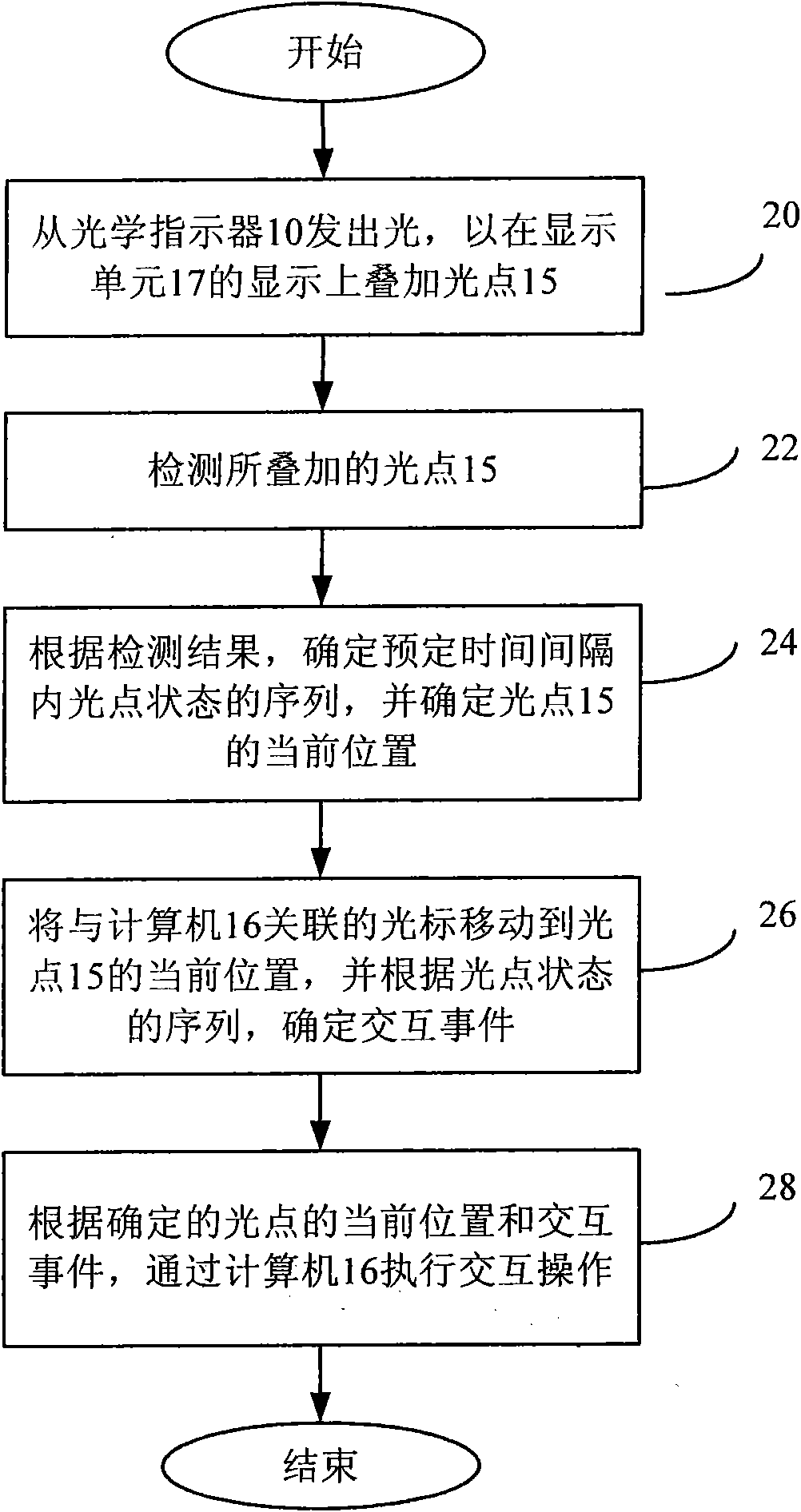
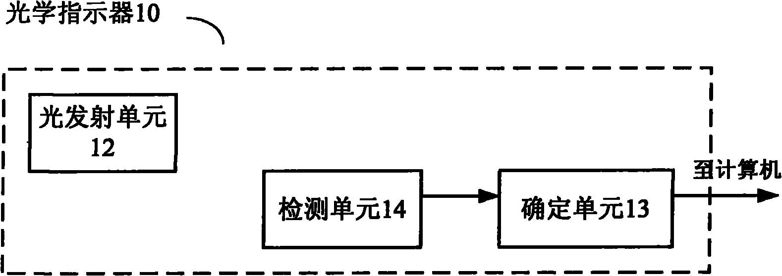
The embodiment of the invention relates to a method for interacting with equipment by utilizing an optical indicator, the optical indicator as well as a presentation method and system adopting the optical indicator. The method for interacting comprises the following steps of: detecting a light spot generated by the optical indicator; determining a sequence of the state of the light spot in a preset time interval according to the detection result; and determining an interaction event according to the sequence of the light spot so as to interact with the equipment. According to the embodiment of the invention, more than one light spot is utilized, and the light spot is mapped to different interaction events according to the sequence of the state of the light spot in the preset time interval, thus more interaction events can be presented. The light spot is easier and simpler to detect, and a detection method can be used for improving the accuracy and the reliability of detection, thus the sequence of the state of the light spot can be mapped into a mouse event and a corresponding mouse signal is generated, so that interaction with a computer is realized.

Description

technical field [0001] Embodiments of the present invention relate to the field of optical indication interaction, and in particular to an optical indicator, a method for interacting with a device using an optical indicator, and a display method and system for using an optical indicator. Background technique [0002] Displays such as projection screens used in conferences are becoming increasingly important for displaying information for everyday use at work or in life. But in some applications, traditional interaction methods are not convenient. Especially in large display environments, traditional desktop input devices such as computer mice and keyboards are not suitable for direct manipulation or control of on-screen objects. For example, due to the need for interaction, a traditional computer using a keyboard and mouse will restrict the speaker to the location of the computer, which is inconvenient. In such cases, some method of remote interaction is required, especial...

Claims


Application Information

Patent Timeline
IPC IPC(8): G06F3/033
Inventor 李仁杰
Owner SHARP KK
Learn More