

Ion mobility spectrometer
A technology of ion mobility spectrometer and ion mobility tube, which is applied to the parts of particle separator tubes, sample introduction/extraction, etc., can solve the problems of unfavorable detection of trace substances, complicated installation and replacement, high detection limit, etc., and achieve simple The effect of efficient detection
- Summary
- Abstract
- Description
- Claims
- Application Information
AI Technical Summary
Problems solved by technology
Method used
Image


Examples
Embodiment Construction
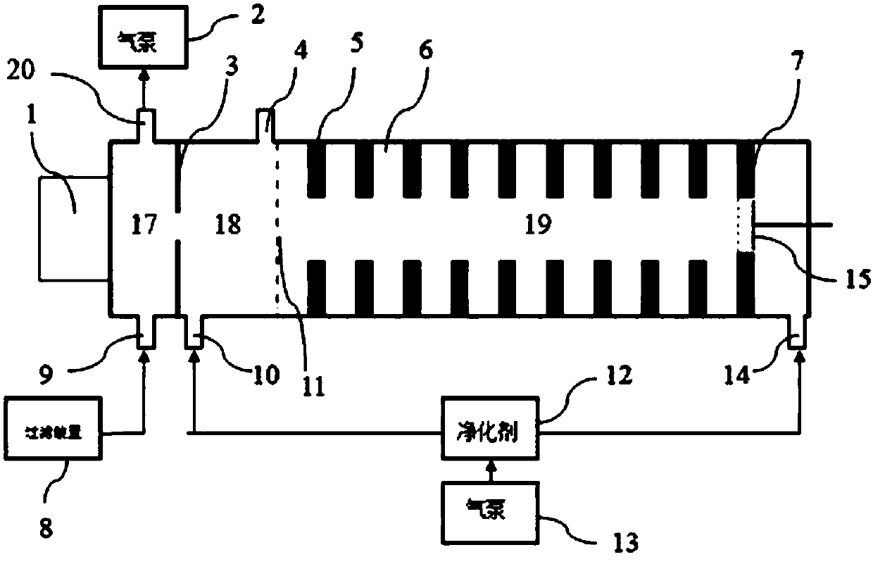
[0009] One aspect of the present invention proposes an ion mobility spectrometer, including an ionization source 1, a dust filter device 8, a sampling pump 2, an ionization zone 17, a reaction zone 18, and a migration zone 19 arranged in sequence along the transfer tube, and the ionization zone 17 and the reaction zone 18 is provided with a plate microporous electrode 3 '. Flat-shaped microporous electrodes Originally flat-shaped electrodes with through-holes in the middle, where 0.1≤through-hole diameter≤3mm. A gas inlet 9 and a gas outlet 20 are provided on the side wall of the ionization zone 17. The gas outlet 20 is connected to the atmosphere through the air pump 2, and the gas inlet 9 is connected to the sample port gas source or the dust filter 8 to the atmosphere. in sample collection. The reaction zone 18 is separated from the migration zone 19 by the ion gate 11 .
[0010] A drift gas inlet 14 is provided on the ion transfer tube near the Faraday disk 15 , and a ca...
PUM
 Abstract
Description
Claims
Application Information