Method and system for realizing timestamp synchronization of active and standby optical line terminals

A technology of optical line terminal and time stamp, applied in time division multiplexing system, selection device of multiplexing system, transmission system, etc., can solve problems such as not supporting holdover function, ONU disconnection, reducing sensitivity, etc. , to achieve the effect of avoiding offline

Inactive Publication Date: 2012-03-14
ZTE CORP
View PDF9 Cites 6 Cited by
  • Summary
  • Abstract
  • Description
  • Claims
  • Application Information

AI Technical Summary

Problems solved by technology

[0005] There is such a problem in the type b protection system: before the switchover, the time stamp counter of the ONU and the time stamp counter on the PON port of the main OLT of the OLT are kept in sync; If the difference between the time stamp in the frame and the local time stamp counter is too large

Method used


Image

  • Method and system for realizing timestamp synchronization of active and standby optical line terminals
  • Method and system for realizing timestamp synchronization of active and standby optical line terminals
  • Method and system for realizing timestamp synchronization of active and standby optical line terminals

Examples


Embodiment Construction
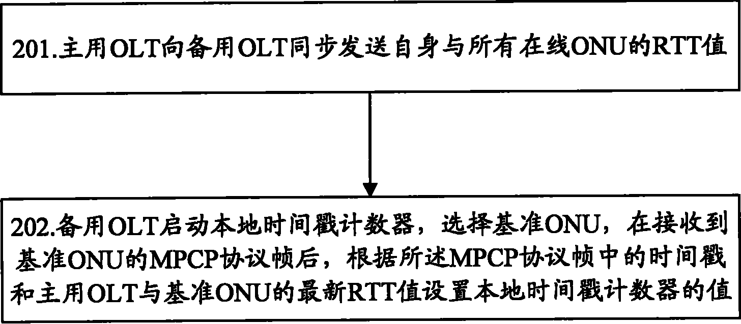
[0032] The basic idea of ​​the present invention is: the active OLT synchronously sends the RTT value of itself and all online ONUs to the standby OLT; the standby OLT selects the reference ONU, after receiving the MPCP protocol frame of the reference ONU, according to the time in the MPCP protocol frame Stamp and the RTT value of the active OLT and reference ONU to set the value of the local time stamp counter.

[0033] The present invention will be described in detail below in conjunction with the accompanying drawings and specific embodiments.

[0034] The present invention realizes the method for synchronizing the time stamp of the active and standby OLT, such as figure 2 As shown, the method includes the following steps:

[0035] Step 201: The active OLT sends the RTT values ​​of itself and all online ONUs synchronously to the standby OLT;

[0036] Specifically, the active OLT calculates the RTT values ​​of itself and all online ONUs according to the received MPCP prot...


PUM


Abstract

The invention discloses a method for realizing the timestamp synchronization of an active optical line terminal (OLT) and a standby OLT. The method comprises that: the active OLT synchronously transmits round trip time (RTT) values with all online optical network units (ONU) to the standby OLT; and the standby OLT selects a reference ONU, and sets a value of a local timestamp counter according to a timestamp in a multipoint control protocol (MPCP) frame and an RTT value of the active OLT with the reference ONU after receiving the MPCP frame of the reference ONU. The invention simultaneously discloses a system for realizing the timestamp synchronization of the active and standby OLTs. By the scheme provided by the invention, timestamp counters of the active and standby OLTs in an Ethernet passive optical network (EPON) backbone optical fiber protection system can be effectively synchronized, and the offline state of the ONU caused by timestamp drift in handover can be avoided, thereby ensuring that the handover can be finished quickly. Moreover, requirements on the ONUs are relatively lower, and compatibility with all conventional ONU equipment can be achieved.

Description

technical field [0001] The invention relates to optical link protection technology, in particular to a method and system for realizing time stamp synchronization of main and standby optical line terminals. Background technique [0002] Ethernet Passive Optical Network (EPON, Ethernet Passive Optical Network) is a new generation of broadband passive optical integrated access technology based on the IEEE802.3-2005 Section 5 standard. The system usually consists of an optical line terminal (OLT, Optical Line Terminal), the user-side optical network unit (ONU, Optical Network Unit) / optical network terminal (ONT, Optical Network Termination) and optical distribution network (ODN, Optical Distribution Network). ODN is composed of passive optical components such as single-mode optical fibers, optical splitters, and optical connectors, and provides optical transmission media for the physical connection between OLT and ONU. ODN is usually a point-to-multipoint structure, that is, on...

Claims


Application Information

Patent Timeline
IPC IPC(8): H04L7/00H04L29/06H04B1/74H04B10/12H04Q11/00
CPCH04Q11/0067H04J3/0641H04Q2011/0079
Inventor 夏顺东
Owner ZTE CORP
Why Eureka
Try Eureka