Microphone control system and method

A technology of a control system and a control method, which is applied in the parts of TV systems, TVs, and color TVs, etc., can solve problems such as difficult control, delay in activity time, affecting speech emotions and performance quality, etc., to achieve precise control, The effect of precise activity flow and timing

Inactive Publication Date: 2012-03-14
SCIENBIZIP CONSULTINGSHENZHENCO
View PDF2 Cites 31 Cited by
  • Summary
  • Abstract
  • Description
  • Claims
  • Application Information

AI Technical Summary

Problems solved by technology

[0003] At present, the microphone is not combined with image detection technology during use. It cannot automatically detect the user's face and mouth position, and adjust to the best radio position and angle according to the user's height. Hands-on adjustment of microphone height and angular position
However, there will always be multiple speakers or performers in most events. Even if a professional sound engineer has been hired to set up the microphone position before the event, it is often caused by the different heights of each speaker or performer. The radio effect is different
If each speaker re-adjusts the height and angle of the microphone before giving a speech, it will not only affect the mood of the speech and the quality of the performance, but also may cause delays in the activity time and make it difficult to control. In addition, the sound collection and amplification effects of the microphones adjusted by the user themselves will also be affected. not able to achieve the best results

Method used


Image

  • Microphone control system and method
  • Microphone control system and method
  • Microphone control system and method

Examples


Embodiment Construction

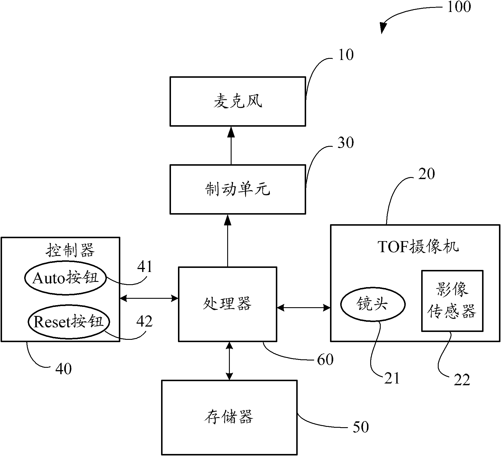
[0018] see figure 1 As shown, it is a hardware structure diagram of a preferred embodiment of the microphone control system 100 of the present invention.

[0019] In this embodiment, the microphone control system 100 includes a microphone 10 , a Time of Flight (TOF) camera 20 , a braking unit 30 , a controller 40 , a memory 50 and a processor 60 . The microphone 10 is connected to the braking unit 30 , and the TOF camera 20 , the braking unit 30 , the controller 40 and the memory 50 are respectively connected to the processor 60 . see Figure 10 As shown, the microphone control system 100 is mounted on a microphone stand 1, and the TOF camera 20 and the microphone 10 are always in the same horizontal position.

[0020] The TOF camera 20 includes a lens 21 and an image sensor 22 , and the image sensor 22 focuses the photographed object through the lens 21 . The image sensor 22 can be a charged coupled device (CCD) or a complementary metal oxide semiconductor (CMOS).

[0021...


PUM


Abstract

The invention provides a microphone control system and a microphone control method. The microphone control system comprises a microphone, a time of flight (TOF) camera, a brake unit, a memory and a processor. The microphone is connected with the brake unit, and the TOF camera, the brake unit and the memory are respectively connected with the processor. The TOF camera continuously shoots a scene in front of the microphone to obtain a scene image. The processor analyzes the scene image to detect a three-dimensional (3D) human-face area, when the microphone is adjusted to a best sound receiving position which is previously stored, a first ratio of the 3D human-face area in the scene image is used for determining a second ratio of a mouth-part position of the 3D human-face area and position information of the mouth-part position in the 3D human-face in the scene image, the brake unit is controlled to automatically adjust a distance between the microphone and the user and a height of the microphone and to adjust the microphone to a best sound receiving position so as to realize the best sound receiving effect.

Description

technical field [0001] The present invention relates to a microphone control system and method. Background technique [0002] Microphone is an energy converter that converts sound into electronic signal. become the original voice. [0003] At present, the microphone is not combined with image detection technology during use, so it cannot automatically detect the position of the user's face and mouth, and adjust it to the best sound-receiving position and angle according to the user's height. Manually adjust the height and angular position of the microphone. However, there will always be multiple speakers or performers in the process of most events. Even if a professional sound engineer has been asked to set the microphone position before the event, it is often caused by the different heights of each speaker or performer. The sound effect is different. If each speaker re-adjusts the microphone height and angle before speaking, it will not only affect the mood of the speec...

Claims


Application Information

Patent Timeline
Patent Type & Authority Applications(China)
IPC IPC(8): H04R29/00H04N5/232
Inventor 李后贤李章荣罗治平
Owner SCIENBIZIP CONSULTINGSHENZHENCO
Why Eureka
Try Eureka