Pneumatic gas-controlled breathing machine

A ventilator and air control technology, which is applied in the field of medical equipment, can solve the problems of inability to accurately adjust the patient's respiratory rate and tidal volume, and achieve the effect of small structure, small valve core diameter, and small movement resistance

Inactive Publication Date: 2014-07-30
于邦仲
View PDF4 Cites 0 Cited by
  • Summary
  • Abstract
  • Description
  • Claims
  • Application Information

AI Technical Summary

Problems solved by technology

Its disadvantage is that it cannot precisely adjust the patient's respiratory rate and tidal volume

Method used


Image

  • Pneumatic gas-controlled breathing machine
  • Pneumatic gas-controlled breathing machine
  • Pneumatic gas-controlled breathing machine

Examples


Embodiment Construction

[0028] The present invention will be described in further detail below in conjunction with accompanying drawing:

[0029] figure 1 One embodiment of the invention is shown.

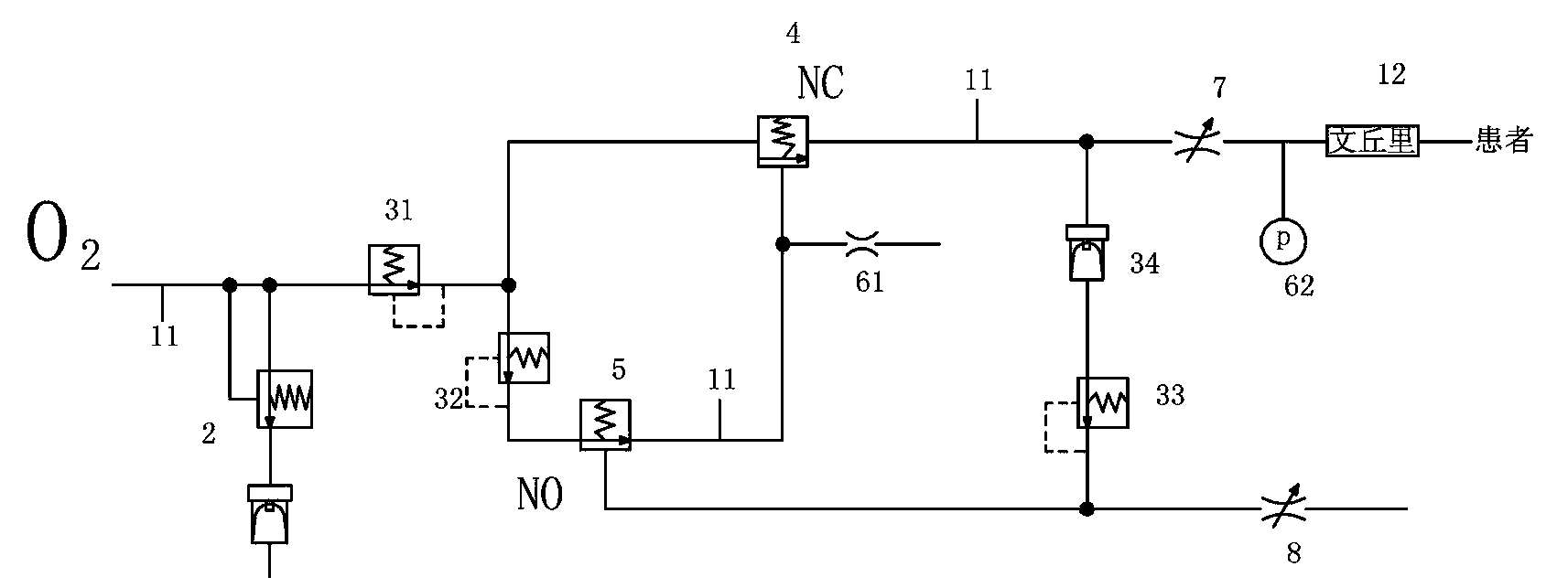
[0030] see figure 1As shown, in this embodiment, the pneumatic air-controlled ventilator includes: a pipeline 11 through which an air source gas with an input pressure greater than 2.8 bar is communicated through an air inlet port, and the pipeline 11 is respectively connected to a gas with an air pressure greater than 2.8 bar. Non-alarm low-pressure alarm valve 2, the first decompression valve 31, the rear end of the first decompression valve 31 is respectively connected to the normally closed valve 4 and the second decompression valve connected in sequence through a three-way pipe (not shown in the figure). Valve 32, normally open valve 5, the normally open valve 5 is connected to the normally closed valve 4 of the control gas cavity through the pipeline 11, and the pipeline 11 between the normally op...


PUM


Abstract

The invention relates to a pneumatic air-controlled ventilator. The pneumatic air-controlled ventilator uses gas as the power source, and the high-pressure gas forms periodic work through the pneumatic valve to supply the patient with an appropriate tidal volume and respiratory rate. The pneumatic air-controlled ventilator only needs to be connected to the air source, and the patient's appropriate respiratory rate and tidal volume can be supplied through the pressure reducing valve and control valve of the pneumatic air-controlled ventilator itself. The control valve of the pneumatic air-controlled ventilator can control the respiratory frequency and tidal volume adjustment. When the pressure of the normally open valve control air chamber rises to the set value, close the normally open valve, and the control gas in the normally closed valve control air chamber is discharged from the air resistance at the same time as the normally open valve is closed, and the normally closed valve resumes closing state, then stop the air supply at the rear end of the normally closed valve, the time period from this moment to the next normally closed valve ventilation is the patient’s exhalation time, and the process from inhalation to exhalation is completed, and the pneumatic air-controlled ventilator works in a cycle like this.

Description

technical field [0001] The invention relates to a medical device, in particular to a pneumatic air-controlled ventilator. Background technique [0002] CN94111392.2 announced a single-air source palm-type emergency ventilator, its purpose is to provide a single air source that is small in size, light in weight, can work normally with only one air source, easy to carry, easy to operate, and suitable for on-site first aid. Air source palm type emergency ventilator. The technical solution is: the single air source palm-type emergency ventilator is specially designed for respiratory rescue in various emergency situations, mainly including air source input port, air flow output port, output flow air resistance, safety valve, air flow Control devices and air-controlled amplifiers, etc., have the advantages of small size, light weight, only one air source can work normally, easy to carry, easy to operate, and low in price. Its shortcoming is: the patient's respiratory rate and ti...

Claims


Application Information

Patent Timeline
Patent Type & Authority Patents(China)
IPC IPC(8): A61M16/00A61M16/20
Inventor 石露李翠萍于邦仲
Owner 于邦仲
Why Eureka
Try Eureka