
Composite piston structure for hydraulic cylinder

A technology for hydraulic cylinders and pistons, which is applied in the field of composite piston structures for hydraulic cylinders, and can solve the problems of increased operating costs of hydraulic cylinder equipment, low troubleshooting rate of piston body equipment, and large energy loss of hydraulic cylinder equipment.

Active Publication Date: 2020-10-30
WUHU EDISON AUTOMATION EQUIP
View PDF5 Cites 0 Cited by
  • Summary
  • Abstract
  • Description
  • Claims
  • Application Information

AI Technical Summary

Problems solved by technology

[0002] At present, the piston structure used in various hydraulic cylinder equipment is a traditional one-piece structure. Although it can meet the needs of use, it also causes a large weight of the piston body, and a low failure repair rate and component replacement rate. On the one hand, The energy loss in the operation of the hydraulic cylinder equipment is relatively large. On the other hand, it also causes serious waste of resources due to the low troubleshooting rate of the piston body equipment, and increases the operating cost of the hydraulic cylinder equipment. Therefore, it is urgent to solve this problem. Develop a brand-new hydraulic equipment to meet the needs of actual use

Method used


Image

  • Composite piston structure for hydraulic cylinder

Examples


Embodiment Construction

[0014] In order to make the technical means, creative features, goals and effects achieved by the present invention easy to understand, the present invention will be further described below in conjunction with specific embodiments.

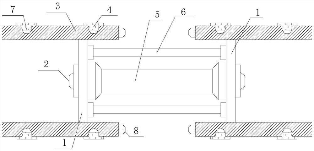
[0015] Such as figure 1 The composite piston structure for a hydraulic cylinder includes a workbench 1, a turntable mechanism 2, a positioning ring 3, an elastic sealing ring 4, a main bearing column 5, and an auxiliary bearing column 6. There are at least two workbenches 1 and two The worktable 1 is symmetrically distributed on both sides of the main bearing column 5 with the axis of the main bearing column 5 as the center, and the workbench 1 and the main bearing column 5 are coaxially distributed, and the turntable mechanism 2 is respectively located on the front end of the workbench 1 It is coaxially distributed with the workbench 1, and the positioning ring 3 is covered outside the workbench 1 and distributed coaxially with the workbench 1, a...


PUM


Abstract

The invention relates to a composite piston structure for a hydraulic cylinder. The composite piston structure comprises at least two workbenches, rotating table mechanisms, positioning rings, elastic sealing rings, a main bearing column and auxiliary bearing columns. The two workbenches are distributed at the two ends of the main bearing column symmetrically about the axis of the main bearing column, the workbenches and the main bearing column are coaxially distributed, the rotating table mechanisms are located on the front end faces of the workbenches and coaxial with the workbenches, the workbenches are wrapped by the positioning rings, the auxiliary bearing columns are evenly distributed around the axis of the main bearing column, and the positioning rings are wrapped by the elastic sealing rings. On one hand, the flexibility of the piston structure can be effectively improved, the piston self weight is reduced, and the piston equipment part fault repair efficiency and replacing ability can be effectively improved; and on the other hand, the using requirements of various hydraulic cylinder bodies with different structures can be effectively met, the moving efficiency of pistons in the hydraulic cylinders can be effectively improved, moving resistance is reduced, the force transfer efficiency is improved, and therefore the purpose of reducing operation energy consumption isachieved.

Description

technical field [0001] The invention relates to a hydraulic device, in particular to a composite piston structure for a hydraulic cylinder. Background technique [0002] At present, the piston structure used in all kinds of hydraulic cylinder equipment is the traditional one-piece structure. Although it can meet the needs of use, it also causes the weight of the piston body to be large, and the failure repair rate and parts replacement rate are low. On the one hand, The energy loss in the operation of the hydraulic cylinder equipment is relatively large. On the other hand, it also causes serious waste of resources due to the low troubleshooting rate of the piston body equipment, and increases the operating cost of the hydraulic cylinder equipment. Therefore, it is urgent to solve this problem. Develop a brand-new hydraulic equipment to meet the needs of actual use. Contents of the invention [0003] Aiming at the deficiencies in the prior art, the invention provides a com...

Claims


Application Information

Patent Timeline
Patent Type & Authority Patents(China)
IPC IPC(8): F15B15/20
CPCF15B15/1447F15B15/1452
Inventor 张庆
Owner WUHU EDISON AUTOMATION EQUIP
Learn More