
Hob type film cutting device

A hob, film technology, applied in the direction of metal processing, etc., can solve the problem of manual auxiliary feeding, accumulation and silt above the feeding port, etc.

Inactive Publication Date: 2012-03-21
BEIJING RES & DESIGN INST OF RUBBER IND
View PDF5 Cites 4 Cited by
  • Summary
  • Abstract
  • Description
  • Claims
  • Application Information

AI Technical Summary

Problems solved by technology

The slender rubber strip is continuously input into the feeding port of the extruder at a certain speed, and is continuously conveyed forward, cut, plasticized and extruded by the rotation of the screw of the extruder. The process is continuous and smooth, which solves the problem of The large film is difficult to enter the feeding port of the extruder due to the volume problem, and often accumulates and blocks above the feeding port, and the drawback of manual auxiliary feeding is required.

Method used


Image

  • Hob type film cutting device
  • Hob type film cutting device
  • Hob type film cutting device

Examples


Embodiment

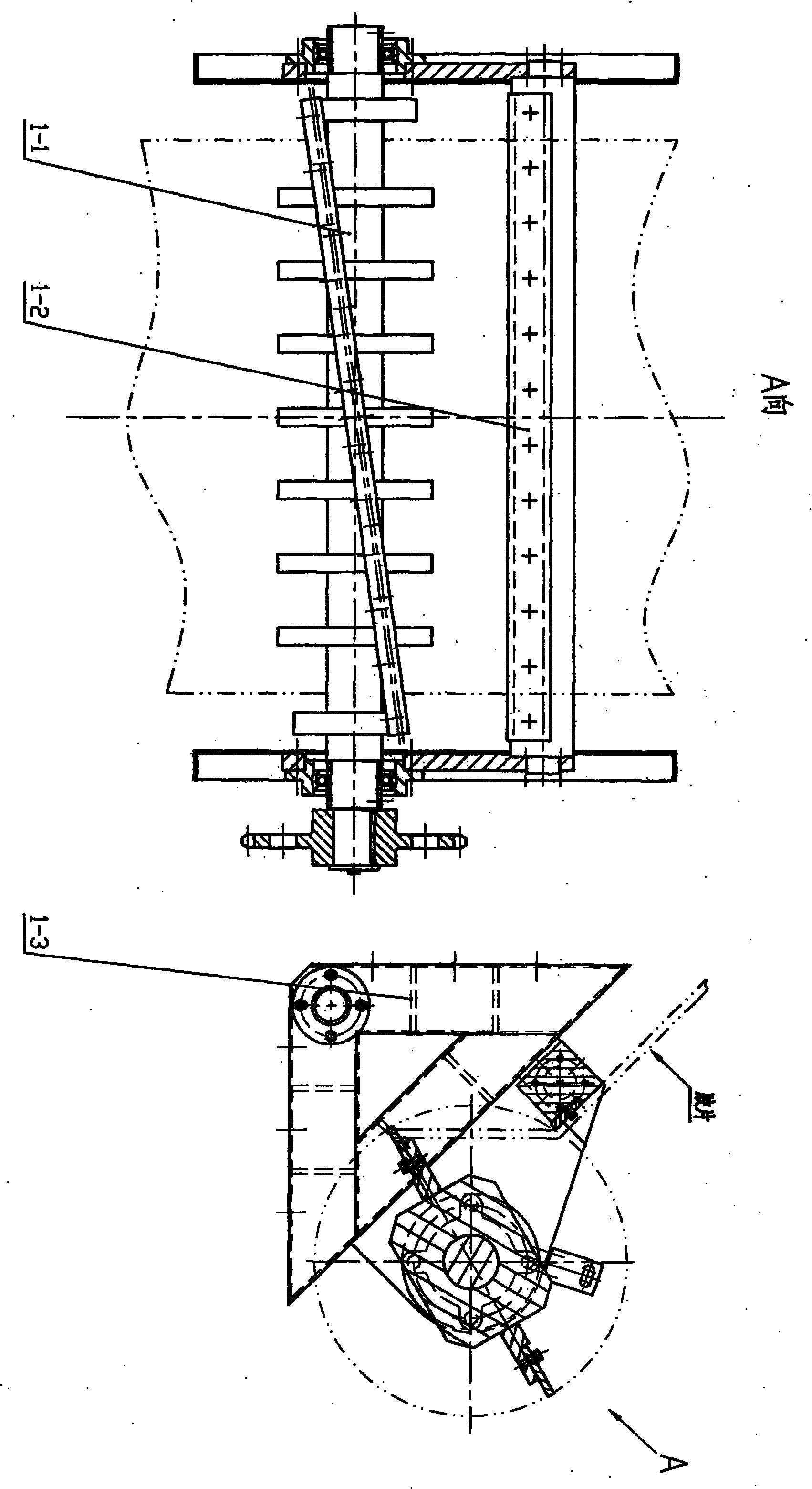
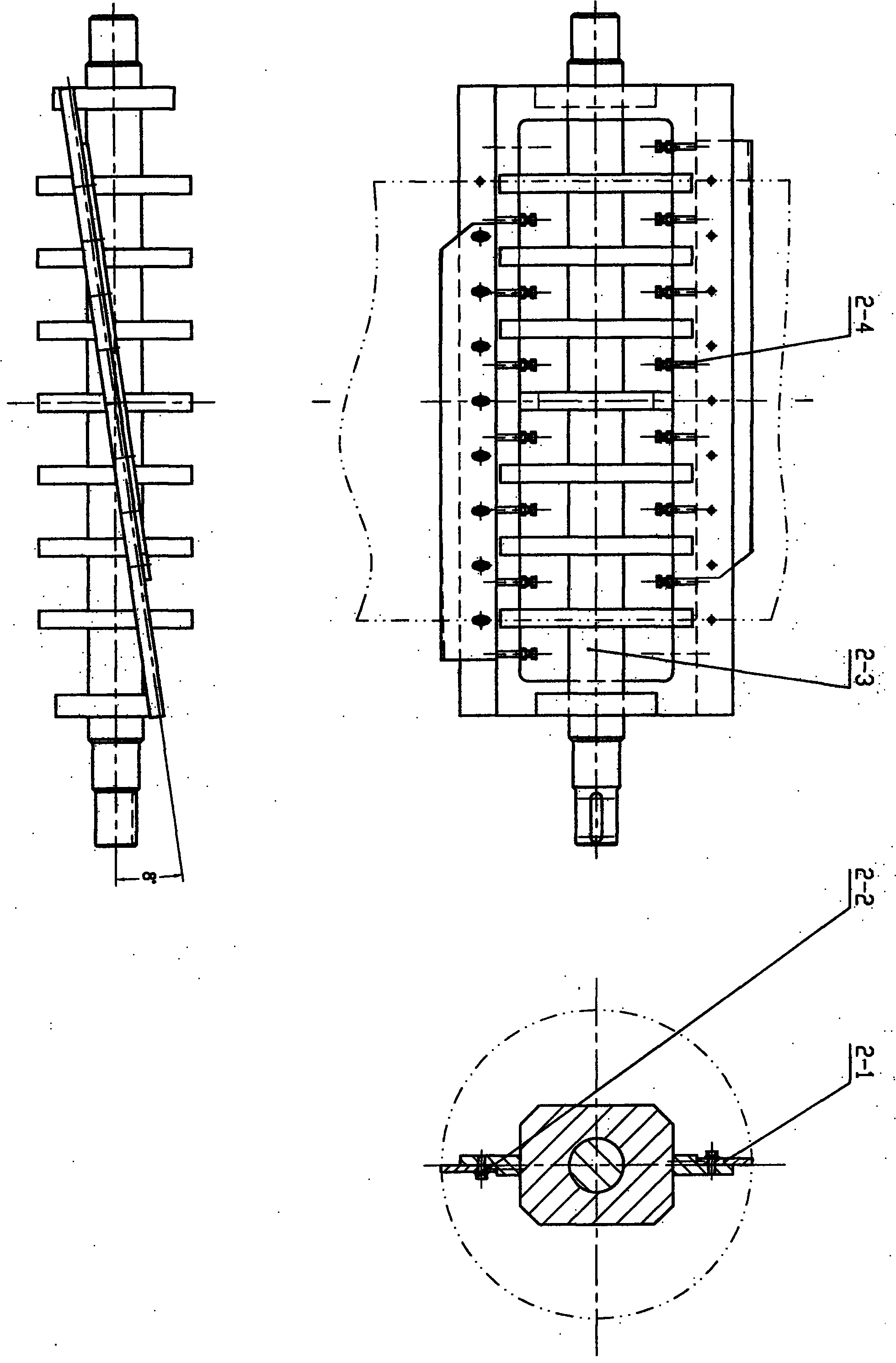
[0018] Embodiment: the hob type film cutting device of the present invention (see attached figure 1 ) is composed of a rolling knife assembly (1-1), a fixed knife assembly (1-2) and a supporting knife rest (1-3) connecting the two. The cut film continuously passes through the gap between the hob and the fixed knife at a certain speed, and the hob assembly driven by the transmission device also rotates continuously at a certain speed, so that the two hobs installed on the hob shaft frame Staggered and fixed knives are tangent, because the two hobs are installed opposite to each other on the frame plane, and their positions are staggered in the direction of the long side of the frame (see attached figure 2 ), the length of each hob is shorter than the width of the film, the superimposed length of the installed two hobs is greater than the width of the film, and the length of the fixed knife is greater than the installed superimposed length of the two hobs, so that each knife in...


PUM


Abstract

The invention relates to a hob type film cutting device, which aims at the continuous feeding problem of an extruding machine and is designed for purposes of improving the production efficiency of the extruding machine and improving the product quality. The hob type film device comprises a hob assembly, a fixed cutter assembly and a support cutter frame, wherein the support cutter frame is connected with the hob assembly and the fixed cutter assembly. The device can cut the film with the width smaller than or equal to 1000mm, the thickness smaller than or equal to 20mm and the length reaching hundred meters into continuous film strips with the width being 20 to 30mm. An eight-degree included angle is formed between a hob and a fixed cutter, when the hob rotates along with a shaft frame, a cutting edge approaches to the fixed cutter along a spiral track and does zero-gap point-contact type relative movement with the fixed cutter, and the film is cut into zigzag slender and continuous film strips. A gap between the hob and the fixed cutter can be regulated through a cutter blade regulation screw bolt. The support cutter frame is an angle frame support beam structure and is connected with the hob assembly and the fixed cutter assembly through a cutter seat arranged above the support cutter frame.

Description

Technical field: [0001] The invention relates to a cutting device for sheet-like rubber compound used in the manufacture of tires and other rubber products, in particular to the design of a hob-type film cutting device. technical background: [0002] Tires or other rubber products are made of dispersed raw materials, namely powdered carbon black, additives, accelerators, block rubber, liquid oil, etc., through progressive processes such as banburying, rubber parts production, molding, vulcanization, inspection, and testing. Manufactured. The basic process of the above-mentioned processing process is banburying, which is to mix the above-mentioned raw materials into a banbury mixer and process them into sheet-like rubber materials with a width of 800mm-1000mm, a thickness of 10mm-20mm, and a length of up to 100 meters for subsequent processing. It is usually necessary to pass this sheet of rubber through extruders of different specifications to extrude various semi-finished ...

Claims


Application Information

Patent Timeline
IPC IPC(8): B26D1/38B26D7/26B29C47/08
Inventor 赵明
Owner BEIJING RES & DESIGN INST OF RUBBER IND
Learn More