Self-aligning hydraulic clutch release bearing

A hydraulic clutch and release bearing technology, applied in clutches, fluid-driven clutches, non-mechanical-driven clutches, etc., can solve the problems of large clutch separation force, strength, and sealing performance that cannot meet the requirements of use, and achieves convenient gear shifting and weight. Light, smooth separation effect

Active Publication Date: 2013-03-27
WUXI MINLIAN AUTOMOBILE PARTS CO LTD
View PDF6 Cites 1 Cited by
  • Summary
  • Abstract
  • Description
  • Claims
  • Application Information

AI Technical Summary

Problems solved by technology

If it is used in medium and light vehicles, its strength and sealing performance cannot meet the requirements of use due to the large clutch separation force of medium and light vehicles.

Method used


Image

  • Self-aligning hydraulic clutch release bearing
  • Self-aligning hydraulic clutch release bearing
  • Self-aligning hydraulic clutch release bearing

Examples


Embodiment Construction

[0013] The specific embodiments of the present invention will be further described below in conjunction with the accompanying drawings.

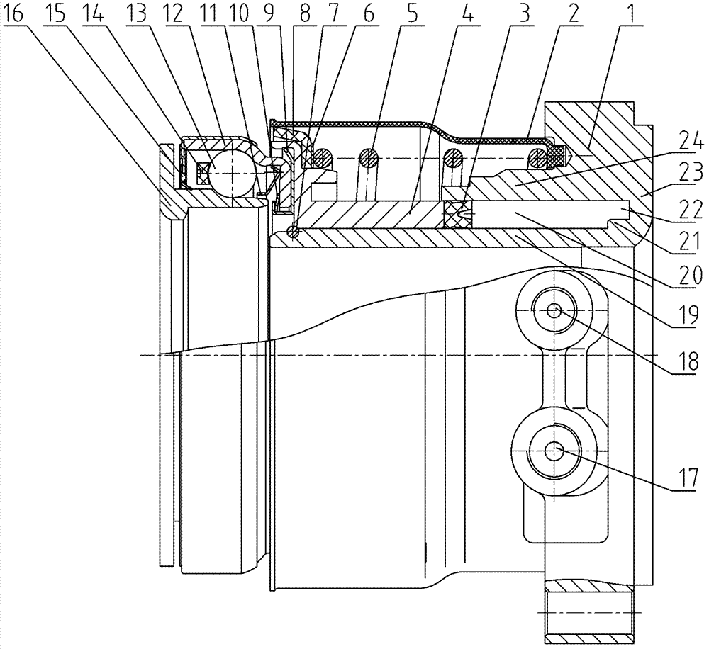
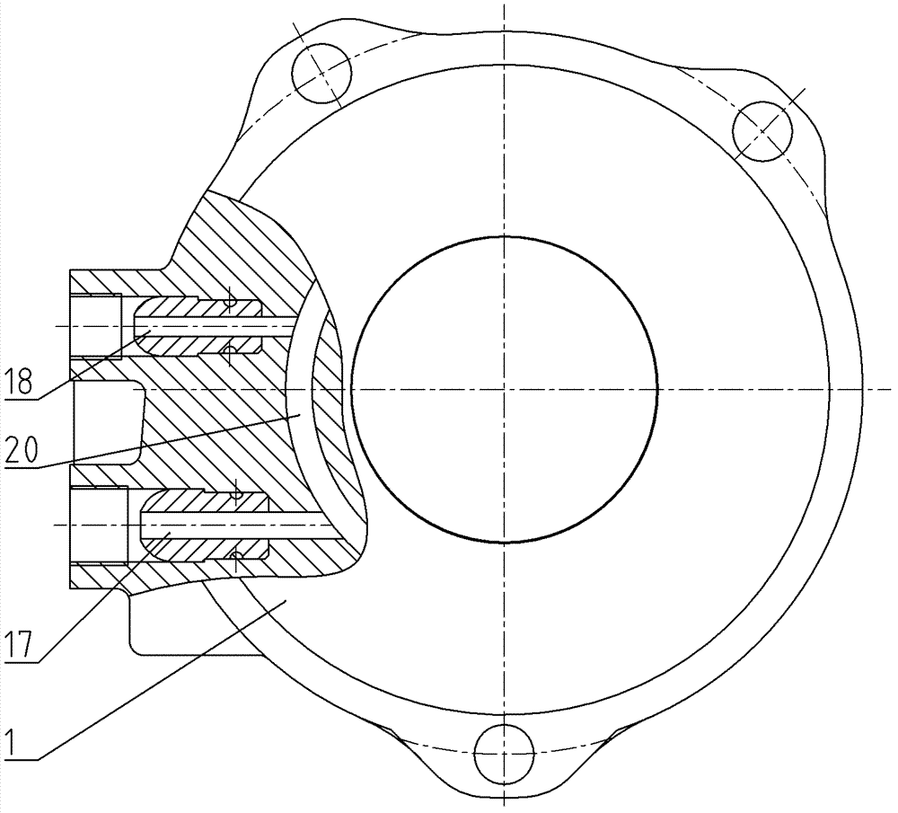
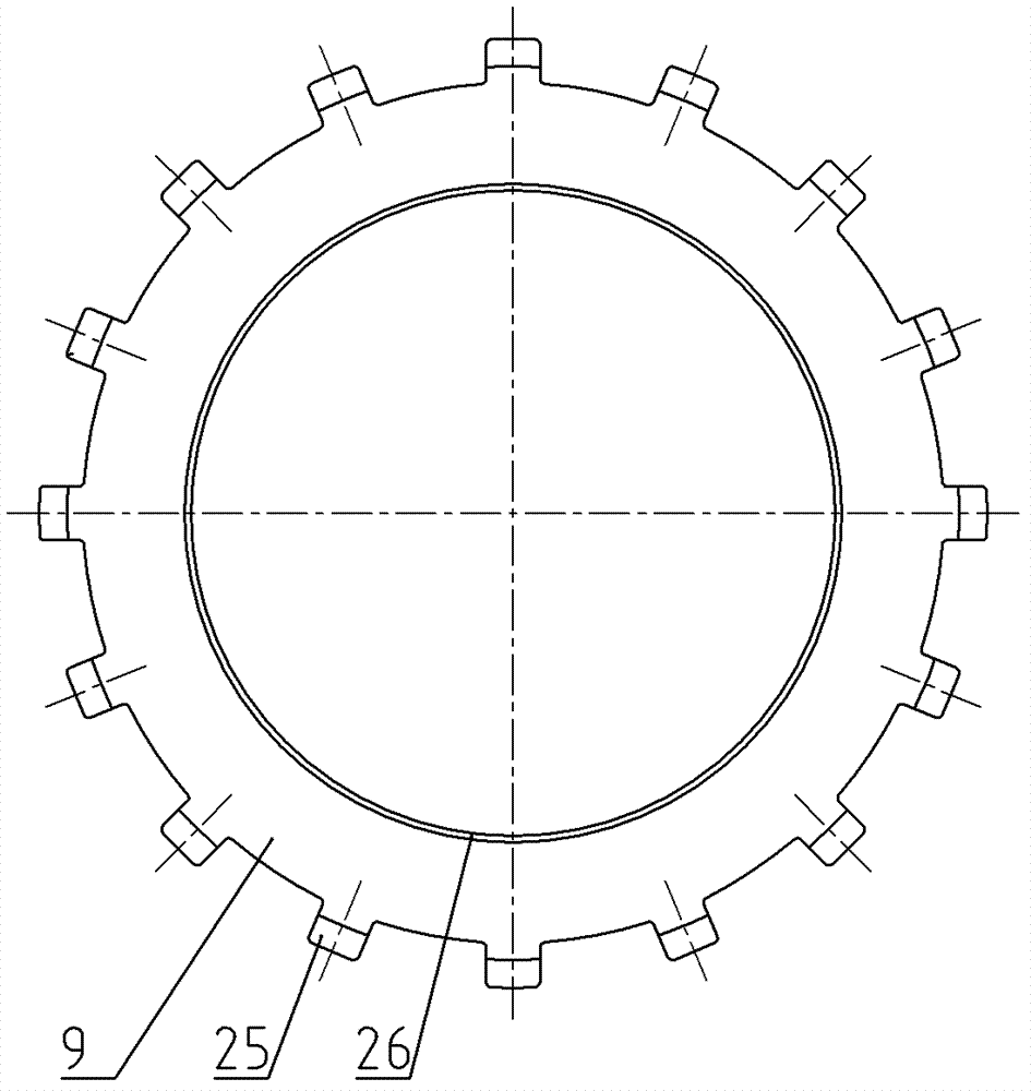
[0014] Figure 1~Figure 4 Including hydraulic cylinder block 1, dust cover 2, hydraulic sealing ring 3, sliding sleeve 4, preload spring 5, support pad 6, circlip 7, rubber dustproof sealing ring 8, toothed connecting piece 9, disc Shaped reed 10, dust cover 11, bearing outer ring 12, ball 13, cage 14, rubber sealing cover 15, bearing inner ring 16, oil inlet channel 17, exhaust channel 18, cylinder inner tube 19, oil chamber 20. Shaft shoulder 21, groove 22, cylinder body 23, cylinder outer cylinder 24, teeth 25, shaft cylinder 26, etc.

[0015] Such as figure 1 , figure 2 As shown, the present invention is a self-aligning hydraulic clutch release bearing, including a hydraulic part and a release bearing part.

[0016] The hydraulic part includes a hydraulic cylinder block 1, a sliding sleeve 4 and a preload spring 5. The hydraulic cy...


PUM


Abstract

The invention relates to a self-aligning hydraulic clutch release bearing comprising a hydraulic cylinder body, a sliding sleeve and a pretension spring, wherein the sliding sleeve is connected with a release bearing; the hydraulic cylinder body comprises a cylinder body main body, a cylinder body outer cylinder and a cylinder body inner cylinder; the sliding sleeve is matched with the interior of an oil chamber of the hydraulic cylinder body in a sliding manner; a disc-shaped spring leaf is mounted on the inner end surface of a bearing outer ring; a tooth-shaped connecting sheet is arranged on the outer end surface of the bearing outer ring; the tooth-shaped connecting sheet is clamped in the concave cavity of the sliding sleeve; the shaft cylinder of the tooth-shaped connecting sheet extends into an inner hole of the bearing outer ring; the disc-shaped spring leaf is riveted on the inner end surface of the bearing outer ring through the shaft cylinder of the tooth-shaped connecting sheet; and the radial clearances are reserved between the tooth-shaped connecting sheet, and the inner hole and the excircle of the bearing outer ring. The invention has the advantages that as bearings are separated from one another under the pushing of hydraulic pressure, the separation is smooth, the operation is easy, and the speed changing and the gear shifting are convenient; and as the hydraulic cylinder body and the sliding sleeve are manufactured integrally, the effects of light weight, high sealing performance and sufficient strength are realized; and as the release bearing adopts the self-aligning structure, damages caused by unbalanced loading can be avoided.

Description

technical field [0001] The invention relates to a clutch release bearing used in medium and light vehicles, in particular to a self-aligning hydraulic clutch release bearing. Background technique [0002] There are two ways to realize clutch separation and combination in the automobile clutch separation system: one is to move the separation sleeve (separation bearing seat) through the separation fork to drive the separation bearing to reciprocate on the shaft sleeve of the gearbox I The movement realizes the separation and combination of the clutch. The release shift fork is in two-point contact with the shift fork support surface on the release sleeve. During frequent separation and combination, especially when the release bearing is pressed against the diaphragm spring release finger to realize clutch separation, under the action of separation force, The contact point is easy to wear, and the separation sleeve is also easy to wear during the long-term reciprocating moveme...

Claims


Application Information

Patent Timeline
Patent Type & Authority Patents(China)
IPC IPC(8): F16D25/12F16C33/76
Inventor 邵济民
Owner WUXI MINLIAN AUTOMOBILE PARTS CO LTD
Why Eureka
Try Eureka