Punch die for commutator segment

A commutator segment and punching die technology, applied in the field of stamping dies, can solve the problems of low production efficiency, easy bending and deformation of the commutator segment, and inability to effectively guarantee the forming quality of the commutator segment, so as to improve production efficiency and be less prone to bending. The effect of deformation and molding quality assurance

Active Publication Date: 2012-03-21
瑞安博宇科技股份有限公司
View PDF5 Cites 5 Cited by
  • Summary
  • Abstract
  • Description
  • Claims
  • Application Information

AI Technical Summary

Problems solved by technology

like figure 1 , 2 , The commutator segment of the hook-type commutator shown in 3 can only be formed by drawing copper and stamping multiple times. Its manufacturing process is as follows. First, the copper is drawn, and the drawn wire is horizontal The cross-sectional shape is the same as the vertical cross-sectional shape of the commutator piece, and then the wire is drawn and stamped on the first stamping die to form the head of the commutator piece, and then stamped on the second stamping die to make the commutation The dovetail foot of the slice is formed and the stamping and cutting of the commutator slice is realized. Since the stamping of the dovetail foot is carried out from the side of the commutator slice, and the thickness of the commutator slice in this direction is thicker, the punched and cut commutator slice The two ends are easy to bend and deform, and the forming quality of the commutator segment cannot be effectively guaranteed
Since the stamping of the commutator segment can only be completed through two stamping dies, the production efficiency is low

Method used


Image

  • Punch die for commutator segment
  • Punch die for commutator segment
  • Punch die for commutator segment

Examples


Embodiment Construction

[0018] The accompanying drawings show the technical solution of the present invention and its embodiments, and the relevant details and working principles of the embodiments will be further described below in conjunction with the accompanying drawings.

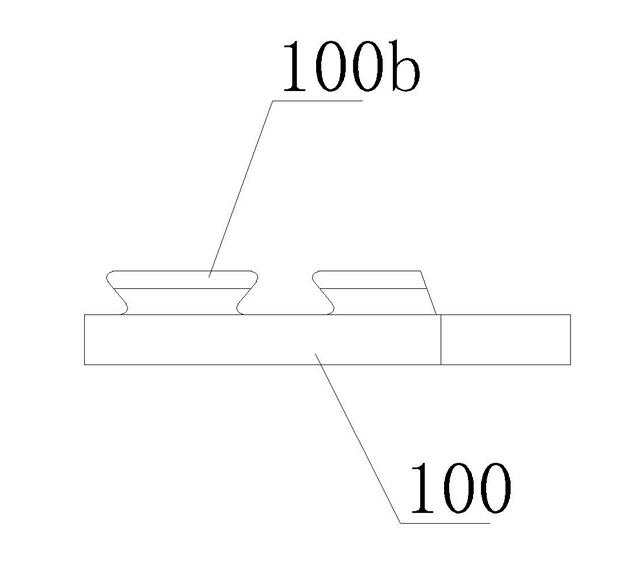
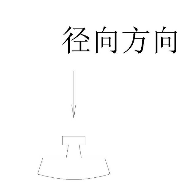
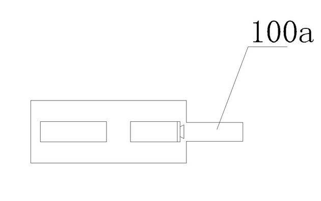
[0019] attached figure 1 , 2 , 3 shows the outline drawing of the stamped commutator piece product, and the vertical cross-sectional shape of the commutator piece 100 is as follows figure 2 As shown, the cross-sectional shape of the drawn wire of the commutator segment is the same as that of the head 100a of the commutator segment and the dovetail foot 100b of the commutator segment.

[0020] as attached Figure 4 , 5 , shown in 6 and 7, the commutator plate punching die of the present invention comprises punch head and punching mouth, and the bottom die 2 of punching die has a feed channel 1 that is arranged laterally, and the facade shape of feed channel 1 is in line with the wire changing plate pull The cross-sectional...


PUM


Abstract

The invention discloses a punch die for a commutator segment. The punch die comprises punches and punching openings, and is characterized in that: a bottom die of the punch die is provided with a transverse feeding channel; the shape of the vertical face of the transverse feeding channel is the same as the shape of the cross section of a drawn wire rod; the punching openings are formed on the bottom die, and comprise punching openings a, b and c; the punching openings a and b are formed in a vertical direction vertical to the feeding channel; the punching opening c is formed in a transverse direction vertical to the feeding channel; the punches corresponding to the punching openings are punches A, B and C; the punches A and B are vertically arranged; and the punch C is transversely arranged. The punch die realizes the rapid punch forming of the commutator segment, and is high in production efficiency and forming quality.

Description

technical field [0001] The invention relates to a stamping die, in particular to a commutator segment stamping die for stamping a commutator segment of a commutator. Background technique [0002] The commutator is widely used in the field of electric tools and motors, and the main part of the commutator is the commutator piece. Such as figure 1 , 2 , The commutator segment of the hook-type commutator shown in 3 can only be formed by drawing copper and stamping multiple times. Its manufacturing process is as follows. First, the copper is drawn, and the drawn wire is horizontal The cross-sectional shape is the same as the vertical cross-sectional shape of the commutator piece, and then the wire is drawn and stamped on the first stamping die to form the head of the commutator piece, and then stamped on the second stamping die to make the commutation The dovetail foot of the slice is formed and the stamping and cutting of the commutator slice is realized. Since the stamping o...

Claims


Application Information

Patent Timeline
Patent Type & Authority Applications(China)
IPC IPC(8): H01R43/06
Inventor 阮志伍杨建旺阮金雨
Owner 瑞安博宇科技股份有限公司
Why Eureka
Try Eureka