Heat dissipation type bus duct

A busway and heat dissipation technology, applied in the field of busway, can solve the problems of busway burning, electrical equipment damage, economic loss, etc., and achieve the effect of improving product performance and saving materials

Inactive Publication Date: 2012-03-21
江苏省成套电气工程技术研究中心
View PDF0 Cites 15 Cited by
  • Summary
  • Abstract
  • Description
  • Claims
  • Application Information

AI Technical Summary

Problems solved by technology

In many places, due to the poor heat dissipation of the bus duct connector, the temperature rise at the joint is too high, resulting in damage to the connector, resulting in the burning of the entire bus duct, and even damage to a large number of electrical equipment, resulting in serious economic losses and potential safety hazards
[0003] Conventional connector busbars are tightly wrapped in a small space by insulating partitions and aluminum profiles, and the heat is transferred to the extern...

Method used


Image

  • Heat dissipation type bus duct
  • Heat dissipation type bus duct
  • Heat dissipation type bus duct

Examples


Embodiment Construction

[0012] The present invention will be further described below in conjunction with accompanying drawing.

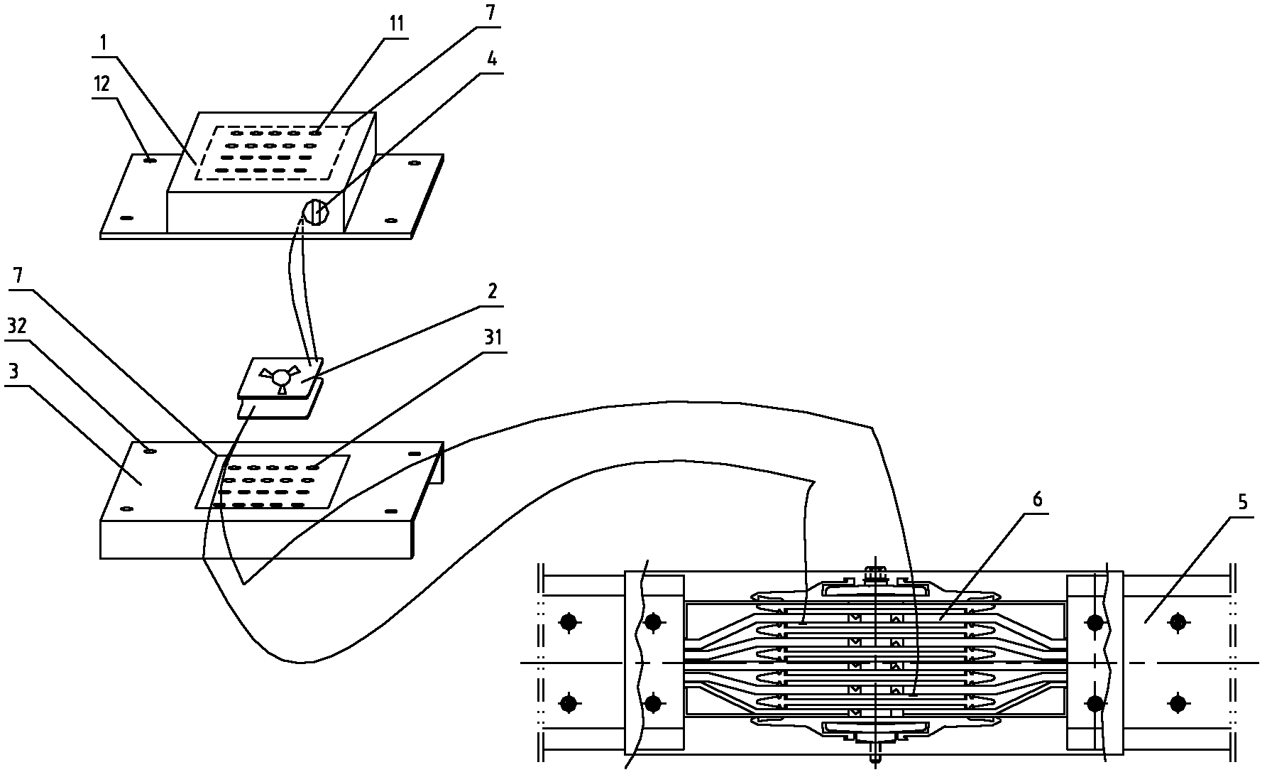
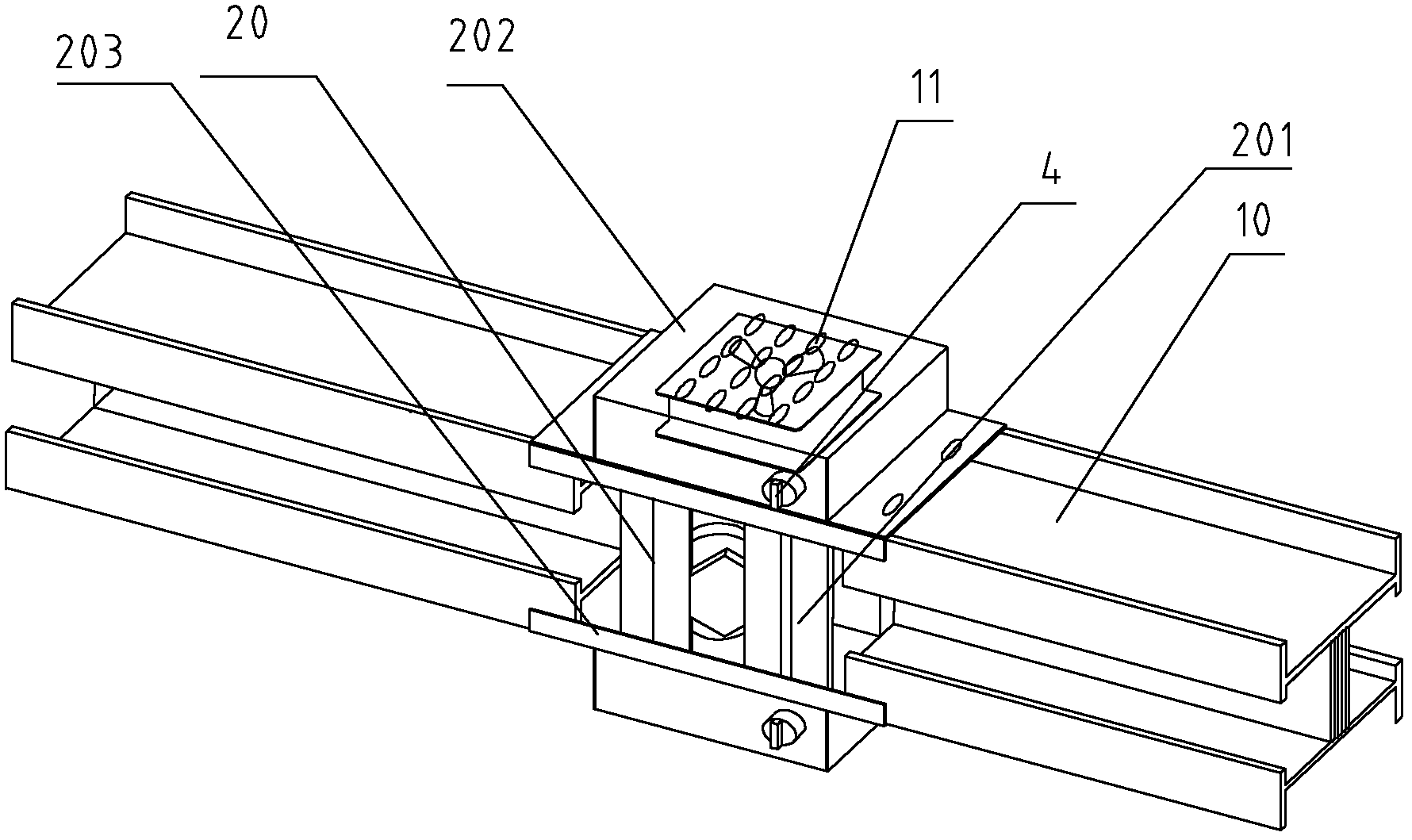
[0013] As shown in the figure, a heat-dissipating busway includes at least two busbar bodies 10, and the adjacent busbar bodies are connected into one body through a connecting device. The connecting device includes a connecting seat 20, and the two ends of the connecting seat 20 are respectively Connected to one end of the corresponding bus bar body 10, the connecting seat 20 includes a column 201, an upper connecting plate 202, and a lower connecting plate 203, and the upper connecting plate 202 has a cross section of The lower connection plate 203 is a groove-shaped member; the upper and lower ends of the column 201 are vertically connected with the upper and lower connection plates 202, 203 respectively, and the column 201 is connected with the upper and lower connection plates 202, 203 presented The upper and lower connecting plates 202, 203 and the side plates of t...


PUM


Abstract

The invention provides a heat dissipation type bus duct. The bus duct comprises at least two bus bodies connected by a connection device. The connection device comprises a connecting seat, two ends of the connecting seat are connected with one end of corresponding bus body respectively, the connecting seat comprises an upright post, an upper connecting plate and a lower connecting plate, the upper and lower ends of the upright post are connected with the upper connecting plate and the lower connecting plate vertically, the bus bodies are connected through the connecting seat comprising the upright post, the upper connecting plate and the lower connecting plate, and ventilation passages are formed between the upper connecting plate and the lateral plates of the bus bodies, as well as the lower connecting plate and the lateral plates of the bus bodies, so as to increase air circulation. Therefore, the heat dissipation effect of a bus is improved and a bus system has a simple structure.

Description

technical field [0001] The invention relates to a bus duct, in particular to a bus duct with good heat dissipation performance, and belongs to the technical field of power transmission equipment. Background technique [0002] With the emergence of modern engineering facilities and equipment, the power consumption of all walks of life is increasing rapidly, especially the emergence of many high-rise buildings and large workshops. The traditional cables used as power transmission wires can no longer meet the requirements in large current transmission systems. The parallel use of multiple cables brings a lot of inconvenience to the site installation and construction connection. As a new type of power distribution wire, the plug-in bus duct has emerged at the historic moment. Compared with the traditional cable, it fully demonstrates its superiority in the transmission of large currents. The contact resistance and temperature rise of the joints at both ends of the slot and the ...

Claims


Application Information

Patent Timeline
IPC IPC(8): H02G5/04H02G5/10
Inventor 宋振达陈荣姚恒祥冯银高中艳印赛虎
Owner 江苏省成套电气工程技术研究中心
Why Eureka
Try Eureka