Heat-dissipation energy-saving type bus duct

A technology of bus duct and heat dissipation column, applied in the field of heat-dissipating energy-saving bus duct, can solve the problems of busbar temperature rise, economic loss, busbar duct burning, etc. The effect of traffic

Inactive Publication Date: 2017-09-19
JIANGSU ONEQ ELECTRICAL APPLIANCE GRP
View PDF4 Cites 0 Cited by
  • Summary
  • Abstract
  • Description
  • Claims
  • Application Information

AI Technical Summary

Problems solved by technology

In many places, due to the poor heat dissipation of the busway, the temperature rise of the busbar is too high, resulting in the burning of the entire busway, and even a large number of electrical equipment, causing serious economic losses and potential safety hazards
At present, the commonly used solution is to increase the cross-section of the busbar connecting the busway. This method increases the cost and the effect is not good.

Method used


Image

  • Heat-dissipation energy-saving type bus duct
  • Heat-dissipation energy-saving type bus duct
  • Heat-dissipation energy-saving type bus duct

Examples


Embodiment Construction

[0022] The present invention will be described in detail below in conjunction with the accompanying drawings.

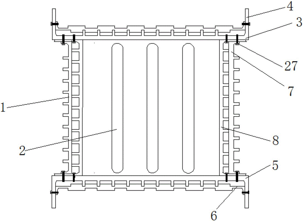
[0023] As shown in the figure, a heat-dissipating and energy-saving bus duct includes a shell and a copper bar; the shell includes a first upper cover, a second upper cover, a first lower cover, a second lower cover, a first side plate, The second side plate, the first upper cover plate and the first lower cover plate are vertically symmetrical, and the two first side plates are fixed between the first upper cover plate and the first lower cover plate by bolts;

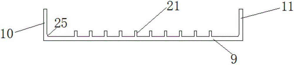
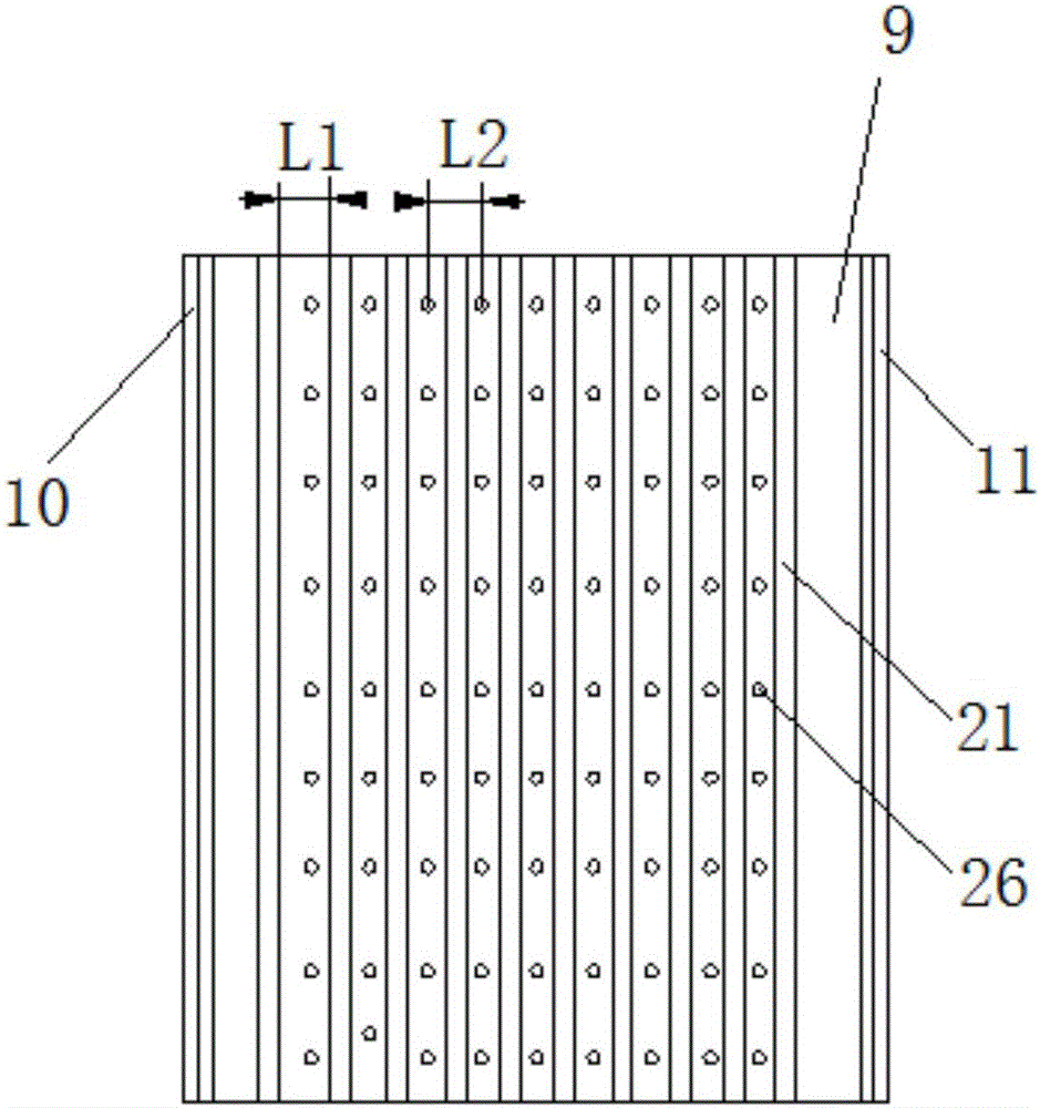
[0024] The structure and size of the first upper cover plate and the first lower cover plate are the same. The first upper cover plate includes a first plate, a second plate, and a third plate, and the second plate and the third plate are respectively fixed on the two sides of the first plate. side, making the first side plate into a "U"-shaped structure; there are ten rows of first heat dissipation columns ...


PUM


Abstract

The invention relates to a heat-dissipation energy-saving type bus duct. A first side plate, a second side plate, a first upper cover plate, a first lower cover plate, a second upper cover plate and a second lower cover plate of a housing are respectively provided with a heat dissipation column, thereby increasing the heat dissipation area, and enabling the heat generated by a conductive strip to be quickly dissipated. The second upper and lower cover plates are provided with heat dissipation bosses, thereby further increasing the heat dissipation area, maintaining the smaller temperature rise of a bus, reducing the energy consumption, and increasing the current carrying capacity of the bus duct. The first side plate, the first upper cover plate and the lower cover plate are provided with a plurality of heat dissipation holes, thereby further improving the heat dissipation performance of the bus duct, and solving a problem of sharp temperature rise of the bus caused by the excessively high environment temperature and the short-cycle and overloaded operation of the bus duct. Therefore, the temperature of a copper bar is reduced, the current carrying capacity of the copper bar is improved, and the purpose of saving energy and reducing consumption is achieved.

Description

technical field [0001] The invention relates to the technical field of power distribution equipment, in particular to a heat-dissipating and energy-saving busway. Background technique [0002] Modern high-rise buildings and large workshops require a huge amount of electric energy, and in the face of the huge loads requiring hundreds of thousands of amperes of strong current, it is necessary to choose safe and reliable conduction equipment, and the busbar system is a good choice. The busway system is a power distribution device for efficient current transmission, especially to meet the needs of economical and reasonable wiring of increasingly taller buildings and large-scale factories. The most important performance index in the busway is "temperature rise". The temperature rise of the busway directly affects the operation quality of the entire power transmission and distribution system. The higher the temperature rise of the busway, the higher the operating temperature of th...

Claims


Application Information

Patent Timeline
IPC IPC(8): H02G5/06H02G5/10
CPCH02G5/06H02G5/10
Inventor 马纪财马松涛
Owner JIANGSU ONEQ ELECTRICAL APPLIANCE GRP
Why Eureka
Try Eureka