Method for manufacturing torsion beam and torsion beam
A manufacturing method and technology of torsion beams, which are applied in the manufacture of torsion beams and the field of torsion beams, can solve the problems of large pipe length restrictions, unfavorable productivity, cost, unfavorable production costs, etc., and achieve reduction of tensile residual stress and fatigue The effect of increasing strength
- Summary
- Abstract
- Description
- Claims
- Application Information
AI Technical Summary
Problems solved by technology
Method used
Image
Examples
Embodiment 1
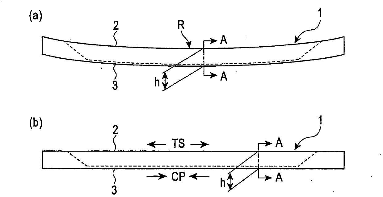
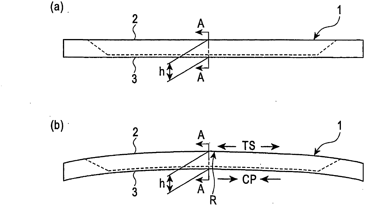
[0097] As embodiment 1, the tube body of the tube blank (the original form is a round tube) shown in Table 1 is placed on the figure 1 or figure 2 In the embodiment shown, torsion beams were manufactured by molding under different processing conditions as shown in Table 2, and the durability life (number of times) was studied by performing the same fatigue test (fatigue test) as above on the manufactured torsion beams. Table 2 shows the results. As can be seen from Table 2, the examples of the present invention exhibited extremely high durability life compared to the comparative examples, and also did not cause shape defects.
Embodiment 2
[0099] As Example 2, the tube body of the tube blank (the original form is a round tube) shown in Table 1 is subjected to different processing conditions as shown in Table 3 in any embodiment of the above-mentioned present invention (2) to (9). A torsion beam was fabricated by performing forming processing, and the same fatigue test as above was performed on the manufactured torsion beam to study the endurance life (number of times). Table 3-1 to Table 3-4 show the results.
[0100] From Table 3-1 to Table 3-4, it can be seen that the example of the present invention exhibited an extremely high durability life compared with the comparative example, and did not cause shape defects. In addition, the results of obtaining the above-mentioned γ by the above-mentioned measuring method are collectively described in Tables 3-1 to 3-4. In the example of the present invention, γ was suppressed to 50% or less.
[0101] [Table 1]
[0102]
[0103] [Table 2]
[0104]
[0105] [Ta...
Embodiment approach
[0116] Implementation column (N): Formed by (N) of the present invention, (N * ): In the present invention (N), molding is performed in such a manner that εa is outside the scope of the present invention
[0117] hydraulic bar -: No hydraulic load, (N): Combined hydraulic load in the present invention (N)
[0118] 1: Apply hydraulic pressure to the inside of the pipe from the state where the bend (bend straightening) with the bottom line as the inside of the bend is maintained until the load is removed
[0119] 2: In the stage from before the start of forming process to before unloading after bending and straightening (all stages of forming process), additional hydraulic pressure is added in the pipe
PUM
| Property | Measurement | Unit |
|---|---|---|
| tensile strength | aaaaa | aaaaa |
| thickness | aaaaa | aaaaa |
| length | aaaaa | aaaaa |
Abstract
Description
Claims
Application Information
 - R&D
- Intellectual Property
- Life Sciences
- Materials
- Tech Scout
- Unparalleled Data Quality
- Higher Quality Content
- 60% Fewer Hallucinations
Browse by: Latest US Patents, China's latest patents, Technical Efficacy Thesaurus, Application Domain, Technology Topic, Popular Technical Reports.
© 2025 PatSnap. All rights reserved.Legal|Privacy policy|Modern Slavery Act Transparency Statement|Sitemap|About US| Contact US: help@patsnap.com


