Strengthening method and strengthening device of rounded portion of crankshaft

A technology of strengthening device and fillet, applied in metal processing equipment and other directions, can solve the problem of not being able to obtain the effect, and achieve the effect of reducing the tensile residual stress

Active Publication Date: 2019-03-19
HONDA MOTOR CO LTD
View PDF12 Cites 0 Cited by
  • Summary
  • Abstract
  • Description
  • Claims
  • Application Information

AI Technical Summary

Problems solved by technology

[0004] However, in the technology described in Japanese Patent No. 3899246, the above-mentioned effects cannot be obtained.

Method used


Image

  • Strengthening method and strengthening device of rounded portion of crankshaft
  • Strengthening method and strengthening device of rounded portion of crankshaft
  • Strengthening method and strengthening device of rounded portion of crankshaft

Examples


Embodiment Construction

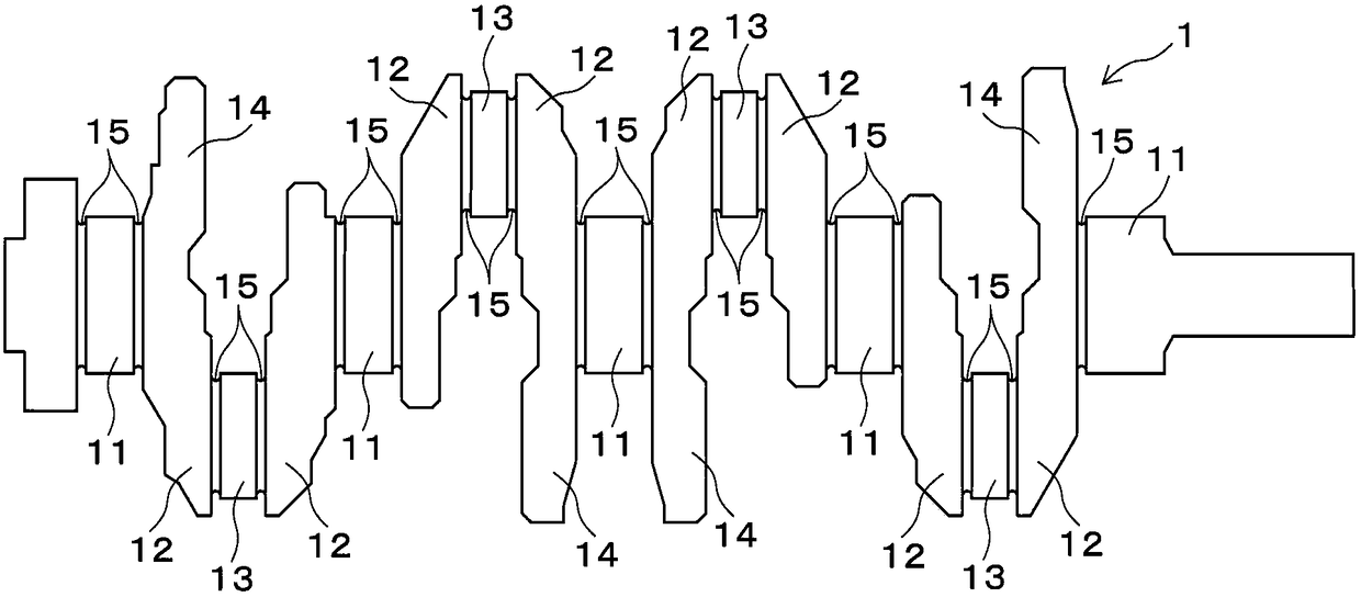
[0025] Hereinafter, one embodiment of the present invention will be described with reference to the drawings. figure 1 It is a side view showing the crankshaft 1 strengthened in this embodiment. The crankshaft 1 is formed by hot forging, and a crank arm 12 protruding radially is formed on a journal pin 11 as a rotating shaft, and a crank pin 13 is bridged at the ends of a pair of crank arms 12. A balance weight 14 is formed at the other end of one of the arms 12 . At both corners of each of the journal pins 11 and the crank pin 13 , rounded corners 15 formed of grooves having a substantially semicircular cross-section are formed.

[0026] figure 2 It shows a state in which the fillet portion 15 of the crank pin 13 is plastically worked by the lower die 2 and the upper die 3 , and the crankshaft 1 is placed on the lower die 2 so that the crank pin 13 faces the vertical direction. A long first lower punch 21 extending upward is provided on one side of the lower die 2 . In a...


PUM


Abstract

A device for strengthening a fillet part of a crankshaft, not only in a radial direction, but also in an axial direction, is provided. The device is configured to press a pressing member from a direction perpendicular to an axis line of a pin part or a journal part, against a portion in a circumferential direction of the fillet part of the pin part or the journal part, which is configured to receive at least one of bending load and torsional stress at the maximum degree, thereby applying compressive residual stress. The device includes a holder 52, which has a slope surface 55 at an end thereof, and a pressing piece 60, which has a sliding surface 61 that is slidable along the slope surface 55 and has a protrusion 62 that is finable to the fillet part. The slope surface 55 is uniformly tilted relative to the pressing direction of the pressing piece 60 so as to face the fillet part.

Description

technical field [0001] The present invention relates to a strengthening method and a strengthening device for strengthening a fillet portion of a crankshaft, and particularly relates to a technique for strengthening a fillet portion not only in the radial direction but also in the axial direction. Background technique [0002] For example, a crankshaft has a journal pin and a crank pin, a large end portion of a connecting rod is rotatably supported by the crank pin, and the journal pin is rotatably supported by a journal bearing of the engine block. Grooves (rounded corners) having a semicircular cross-section are formed at the corners of the crank pin and the journal pin to avoid interference with mating components. The rounded part is a part with low strength, and since it receives a large bending moment when the internal combustion engine explodes, it is desirable to pin the top of the rounded part (in the case of an inline 4 cylinder, the positions where the phases are 0...

Claims


Application Information

Patent Timeline
Patent Type & Authority Patents(China)
IPC IPC(8): B21J5/02
CPCB21J5/02
Inventor 田中利享三浦大介吉村拓郎竹内丰越野大介
Owner HONDA MOTOR CO LTD
Why Eureka
Try Eureka