Vehicle-posture adjusting system tire load control method

A technology of adjustment system and control method, applied in vehicle components, elastic suspension, suspension and other directions, can solve problems such as unreasonable wheel load distribution, and achieve the effect of reasonable pressure distribution

Inactive Publication Date: 2012-03-28
CHINA NORTH VEHICLE RES INST
View PDF5 Cites 29 Cited by
  • Summary
  • Abstract
  • Description
  • Claims
  • Application Information

AI Technical Summary

Problems solved by technology

[0004] The purpose of the present invention is to provide a method for controlling the tire load of the vehicle attitude adjustment system. Through the monitoring of the oil cylinder displacement and pressure information by the controller, the pressure distribution of the

Method used


Image

  • Vehicle-posture adjusting system tire load control method
  • Vehicle-posture adjusting system tire load control method
  • Vehicle-posture adjusting system tire load control method

Examples


Embodiment 1

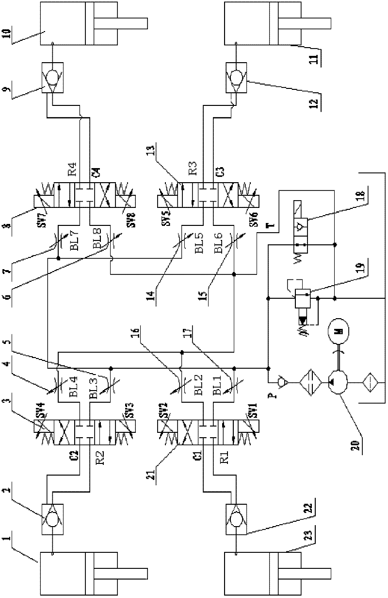
[0042] Such as Figure 1-3 As shown, a vehicle attitude adjustment system tire load control method of the present invention, the vehicle attitude adjustment system includes: suspension, fuel tank, hydraulic pump 20, hydraulic control check valve 22, hydraulic control check valve 2, hydraulic control Check valve 9, hydraulic control check valve 13, three-position four-way proportional directional control valve 21, three-position four-way proportional directional control valve 3, three-position four-way proportional directional control valve 8, three-position four-way proportional directional control valve 13. Adjustable throttle valve 17, adjustable throttle valve 16, adjustable throttle valve 5, adjustable throttle valve 4, adjustable throttle valve 7, adjustable throttle valve 6, adjustable throttle valve 14, adjustable throttle valve 15, Oil cylinder 23, oil cylinder 1, oil cylinder 10, oil cylinder 11, two-position two-way valve 18;

[0043] The hydraulic pump 20 is driven...

Embodiment 2

[0062] Such as Figure 1-3 As shown, a tire load control method of a vehicle posture adjustment system invented in this example, the system and steps are basically the same as those in Embodiment 1, the difference is that:

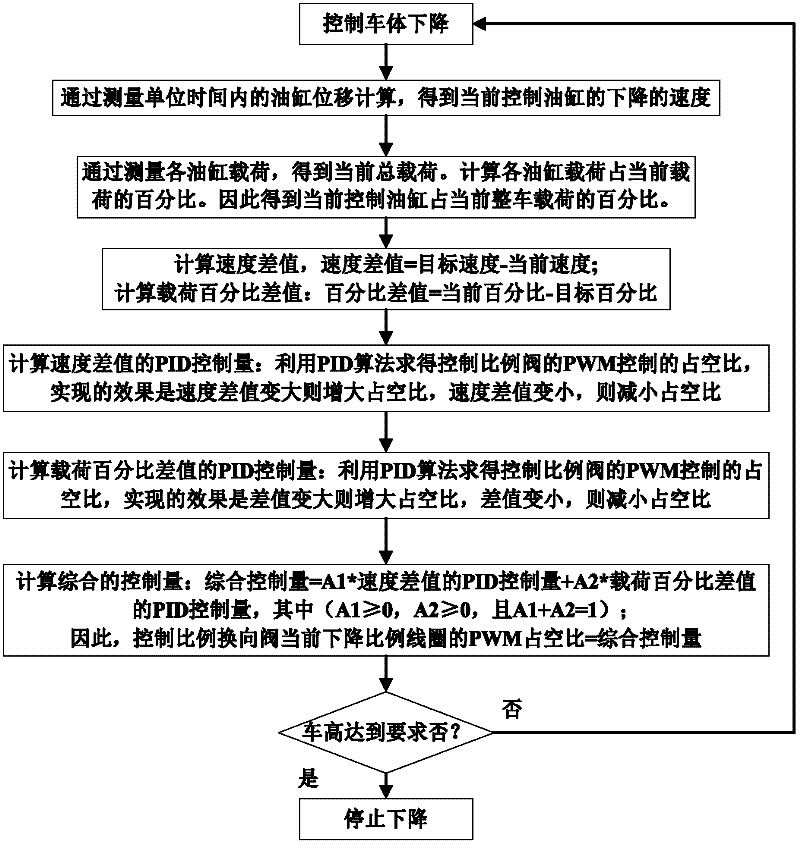
[0063]Step 3. Set a basic difference. The value of the basic difference depends on the control accuracy requirements of the vehicle height adjustment and the accuracy that the sensor can achieve. The result obtained by comparing the detected current vehicle height with the target vehicle height and the basis The differences are compared and processed in three cases.

[0064] a. When the result obtained by comparing the detected current vehicle height with the target vehicle height is greater than the base difference, the vehicle height is adjusted downward, and the adjustment method and steps are completely consistent with embodiment 1;

[0065] b. When the detected current vehicle height is compared with the target vehicle height and the result obtained ...


PUM


Abstract

The invention relates to a hydraulic and control method, in particular to a vehicle-posture adjusting system tire load control method, which is characterized in that: an adjusting system comprises a suspension, an oil tank, a hydraulic pump, a hydraulic control retaining valve, a three-level four-way proportional reserving valve, an adjustable throttling valve, oil cylinders and a two-level two-way valve; a target height, a target velocity and a target load percentage of a vehicle under a normal road driving state are preset, then the current vehicle height is detected, the detected current vehicle height is compared with the target vehicle height for analysis, and the treatment is carried out in an ascending situation, a descending situation and a non-adjusting situation according to thecomparison result of the detected current vehicle height and the target height. A controller is used for monitoring the information of displacement and pressure of the oil cylinders, so the pressure of four suspension oil cylinders can be reasonably distributed, the reasonable distribution of the tire load can be guaranteed during the vehicle posture adjusting process, and the problem that the distribution of the tire load is unreasonable because of the adjustment of the vehicle posture can be solved.

Description

Technical field: [0001] The invention relates to a hydraulic pressure and control method, and more particularly relates to a tire load control method of a vehicle posture adjustment system. Background technique: [0002] Vehicle attitude or height adjustment is widely used in engineering vehicles, off-road vehicles, high-end cars, and military vehicles. At present, the attitude adjustment of the vehicle is generally by measuring the displacement signal of the vehicle height sensor, calculating the difference between the current displacement signal of the vehicle and the command value, and controlling the action of the hydraulic or pneumatic valve to realize the oil filling and discharging of the oil cylinder or cylinder. Deflate to achieve vehicle height adjustment. By adjusting the height of the vehicle, the ability of the vehicle to adapt to the road conditions can be improved to the greatest extent, and the off-road passing ability and slope driving ability of the vehicl...

Claims


Application Information

Patent Timeline
IPC IPC(8): B60G17/015
Inventor 宋慧新贾川陈宇侯友山肖洁赵宁曹宇
Owner CHINA NORTH VEHICLE RES INST
Why Eureka
Try Eureka