Dynamic stall control method based on dynamic sagging of leading edge of wing

A wing leading edge and dynamic stall technology, applied in the direction of heat reduction structure, etc., can solve the problems of low jet flow, single optimal working condition of vortex generator, and weak control effect

Active Publication Date: 2021-05-28
BEIJING INSTITUTE OF TECHNOLOGYGY
View PDF6 Cites 0 Cited by
  • Summary
  • Abstract
  • Description
  • Claims
  • Application Information

AI Technical Summary

Problems solved by technology

[0004] Among various dynamic stall flow control technologies, the optimal working condition of the vortex generator is single, which is not sui

Method used


Image

  • Dynamic stall control method based on dynamic sagging of leading edge of wing
  • Dynamic stall control method based on dynamic sagging of leading edge of wing
  • Dynamic stall control method based on dynamic sagging of leading edge of wing

Examples


Embodiment Construction

[0023] The present invention will be described in detail below with reference to the accompanying drawings and examples.

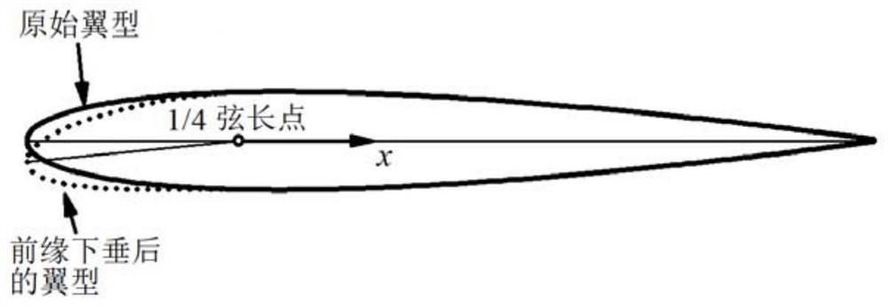
[0024] The invention provides a dynamic stall control method based on the dynamic drooping of the leading edge of the wing. The local effective angle of attack at the small leading edge makes the pressure distribution of the wing more reasonable, reduces the reverse pressure gradient near the leading edge, and makes separation less likely to occur; The edge returns to its original shape from the drooping state, thereby better maintaining the aerodynamic characteristics of the original airfoil.

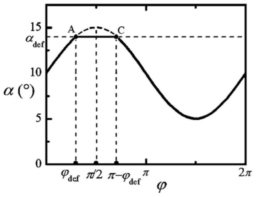
[0025] The drooping mode of the leading edge of the wing is as attached figure 1 shown. attached figure 2 It shows the variation of the angle of attack of the wing as a whole and the leading edge with time, and the horizontal axis represents the phase angle, which is the product of time and angular frequency—φ=ωt, so time can also be represented when the angula...


PUM


Abstract

The invention discloses a dynamic stall control method based on the dynamic sagging of the leading edge of a wing, and belongs to the technical field of aircraft flow control. In the pitching oscillating motion process of the wing, when the attack angle of the wing is increased to a set value, the leading edge of the wing is controlled to droop so as to reduce the local effective attack angle of the leading edge; and in the attack angle reducing process of the wing, the front edge of the wing is controlled to recover from the sagging state, so that the aerodynamic characteristics of the original wing profile are kept. The dynamic stall in the wing pitching oscillation process is effectively controlled by reasonably controlling the dynamic droop of the front edge of the wing.

Description

technical field [0001] The invention belongs to the technical field of aircraft flow control, and in particular relates to a dynamic stall control method based on the dynamic drooping of the leading edge of the wing. Background technique [0002] Dynamic stall refers to the unsteady flow separation and stall phenomenon that occurs during the dynamic motion of aerodynamic components, which may occur in aerodynamic devices such as helicopter rotors and wind turbine blades. For the helicopter in the forward flight state, since the angle of attack of the rotor blades changes periodically (that is, pitch oscillation) when the pitch is changed periodically, and it is in a relatively low incoming flow velocity, it is easy to cause a dynamic stall. occur. Dynamic stall produces pressure fluctuations and load mutations on the upper surface of the wing, which may significantly increase the normal force and generate a large nose-down moment, which has a great impact on the aerodynamic...

Claims


Application Information

Patent Timeline
IPC IPC(8): B64C3/36
CPCB64C3/36
Inventor 雷娟棉勇政牛健平张定金
Owner BEIJING INSTITUTE OF TECHNOLOGYGY
Why Eureka
Try Eureka