Sliding-type bus-bar joint

A busbar, sliding technology, applied in the field of slidable busbar joints, can solve the problem of time-consuming and laborious disassembly, and achieve the effects of improving safety performance, good airtightness, and short time.

Active Publication Date: 2013-04-24
浙江旺隆轨道交通设备有限公司
View PDF6 Cites 0 Cited by
  • Summary
  • Abstract
  • Description
  • Claims
  • Application Information

AI Technical Summary

Problems solved by technology

However, under the obstruction of the busbar, the civil air defense door and the anti-flooding door cannot be completely closed, and special personnel need to be sent into the tunnel to remove a section of the busbar at the civil air defense door and the anti-flooding door from the entire catenary system. When the situation is urgent or when there is a large amount of water, personnel cannot enter the tunnel. Even if they can enter the tunnel, disassembly is time-consuming and laborious due to existing design problems.
[0005] After searching, there is no connecting joint specially used to make one section of the busbar drop automatically from the entire catenary system. Connectors are essential

Method used


Image

  • Sliding-type bus-bar joint
  • Sliding-type bus-bar joint
  • Sliding-type bus-bar joint

Examples


Embodiment Construction

[0028] The following are specific embodiments of the present invention and in conjunction with the accompanying drawings, the technical solutions of the present invention are further described, but the present invention is not limited to these embodiments.

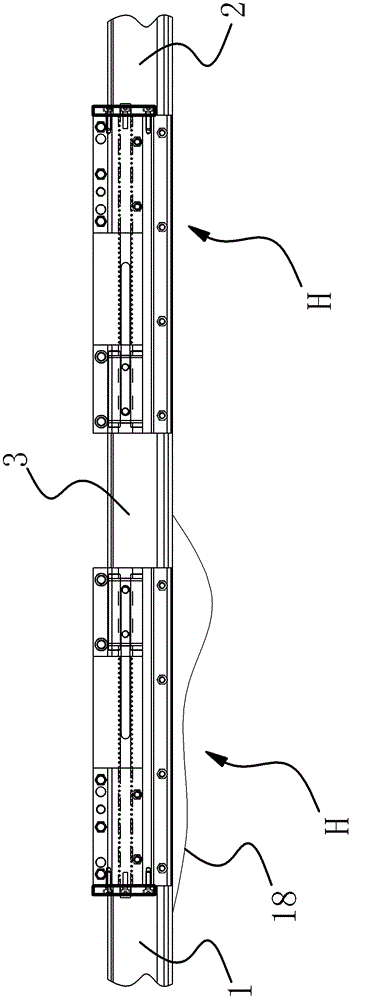
[0029] Such as figure 1 As shown, a rigid catenary disconnectable busbar joint device includes busbar A-end 1, busbar B-end 2 and a connecting section 3 between the two for connection. Between the connecting section 3 and the busbar An electrical connecting strip 18 is also fixed between the A ends 1; the slidable busbar joint H is arranged between the busbar A end 1 and the connecting section 3 and between the busbar B end 2 and the connecting section 3.

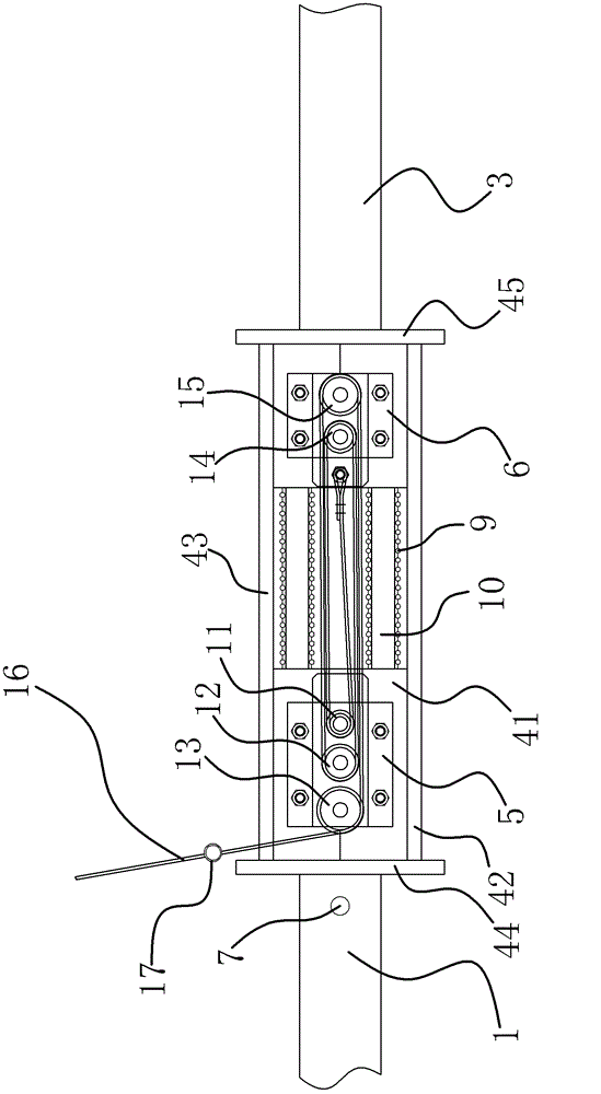
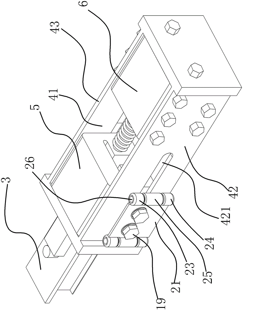
[0030] Such as Figure 2 to Figure 7As shown, the slidable busbar joint H includes a power supply arm bracket with a sliding cavity 41, and a static joint 5 and a moving joint 6 for connection are provided in the sliding cavity 41 of the power supply arm bracket, and t...


PUM


Abstract

The invention provides a sliding-type bus-bar joint and belongs to the technical field of machinery, and the sliding-type bus-bar joint can be used for solving the technical problem that the existing bus-bar joint is not capable of automatically enabling a connection section connected to the bus-bar joint to be separated from the bus-bar joint. The sliding-type bus-bar joint comprises a power supply arm bracket provided with a sliding cavity; the sliding cavity of the power supply arm bracket is internally provided with a static joint and a dynamic joint which are used for connection; the static joint is fixed in the sliding cavity of the power supply arm bracket; the dynamic joint is internally provided with a mounting part; and the dynamic joint is provided with a linking device used for enabling the dynamic joint to slide toward the static joint. The sliding-type bus-bar joint has the advantages of being safer in use, higher in automation, more labor-saving in operation and the like.

Description

technical field [0001] The invention belongs to the technical field of machinery, and relates to a slidable bus bar joint, in particular to a slidable bus bar joint applied to a catenary system. Background technique [0002] With the rapid development of urban rail transit construction in my country, the form of rigid suspension catenary is widely used. It is an important equipment for the power supply of electrified railway locomotives and rail transit vehicles. Its quality directly affects the operation of locomotives. [0003] Rigid suspension catenary is a system composed of contact wires embedded in multiple busbars connected head to tail. Each busbar is connected by a joint, which is generally fixed by bolts and busbars. [0004] However, civil air defense doors are designed in the construction of urban subway tunnels, and anti-flood doors are designed when the tunnel passes under the river. When the rigid suspension catenary encounters special situations of war and se...

Claims


Application Information

Patent Timeline
Patent Type & Authority Patents(China)
IPC IPC(8): B60M1/24
Inventor 宋晔宏徐剑杨波张建根李朝阳肖国军李海洋陈显志程润良
Owner 浙江旺隆轨道交通设备有限公司
Why Eureka
Try Eureka