Terminal for sealed battery and manufacturing method therefor

a technology for sealing batteries and terminals, which is applied in the direction of cell components, cell component details, electrochemical generators, etc., can solve the problems of large variation in the height dimension of the battery, deficient flatness, and increasing the specific requirements of the batteries used in such equipmen

Inactive Publication Date: 2012-03-08
SANYO ELECTRIC CO LTD
View PDF2 Cites 22 Cited by
  • Summary
  • Abstract
  • Description
  • Claims
  • Application Information

AI Technical Summary

Benefits of technology

[0027]With the forming method of such aspect of the invention, a terminal unit for a sealed battery that yields the foregoing advantages can be formed with ease.

Problems solved by technology

With the rapid spread of portable electronic equipment, the specifications required of the batteries used in such equipment have become more demanding year by year.
However, with the terminal unit 50 of the sealed battery described in JP-A-2003-151528, a crimped portion is present on the outside of the battery, and consequently there exist the issues that the end portion 58 of the electrode lead-out pin 57 is deficient in flatness and that there is large variation in the battery height dimension.
However, the terminal unit 60 of the sealed battery set forth in JP-A-2008-251411 requires a huge equipment investment because it is necessary to laser-weld the edges of the circular truncated cone portions 68 of the end face 66 of the crimped terminal 61 to the collector part 65, and this means an increase in the battery cost.
Furthermore, unless such laser welding is performed, crimped portions will be present inside the battery, which means that if a severe external force is imposed in the event of the battery being dropped, etc., conduction faults could occur due to electrolyte entering into the conduction locations in the crimped portions (electrolyte inflow), and if so the internal resistance of the battery could change greatly.
However, the terminal unit of the sealed battery set forth in JP-A-59-41862 has a structure such that electrical conduction between the washer and the concave rivet is effected by spot-welding an electrical lead body to the washer, and the crimping points between the concave rivet and the washer are located inside the battery, which means that if a severe external force is imposed in the event of the battery being dropped, etc., conduction faults could occur due to electrolyte entering the crimping points between the concave rivet and the washer, and if so the internal resistance of the battery could change greatly.

Method used


Image

  • Terminal for sealed battery and manufacturing method therefor
  • Terminal for sealed battery and manufacturing method therefor
  • Terminal for sealed battery and manufacturing method therefor

Examples


Embodiment Construction

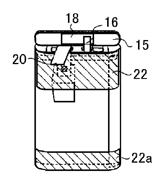
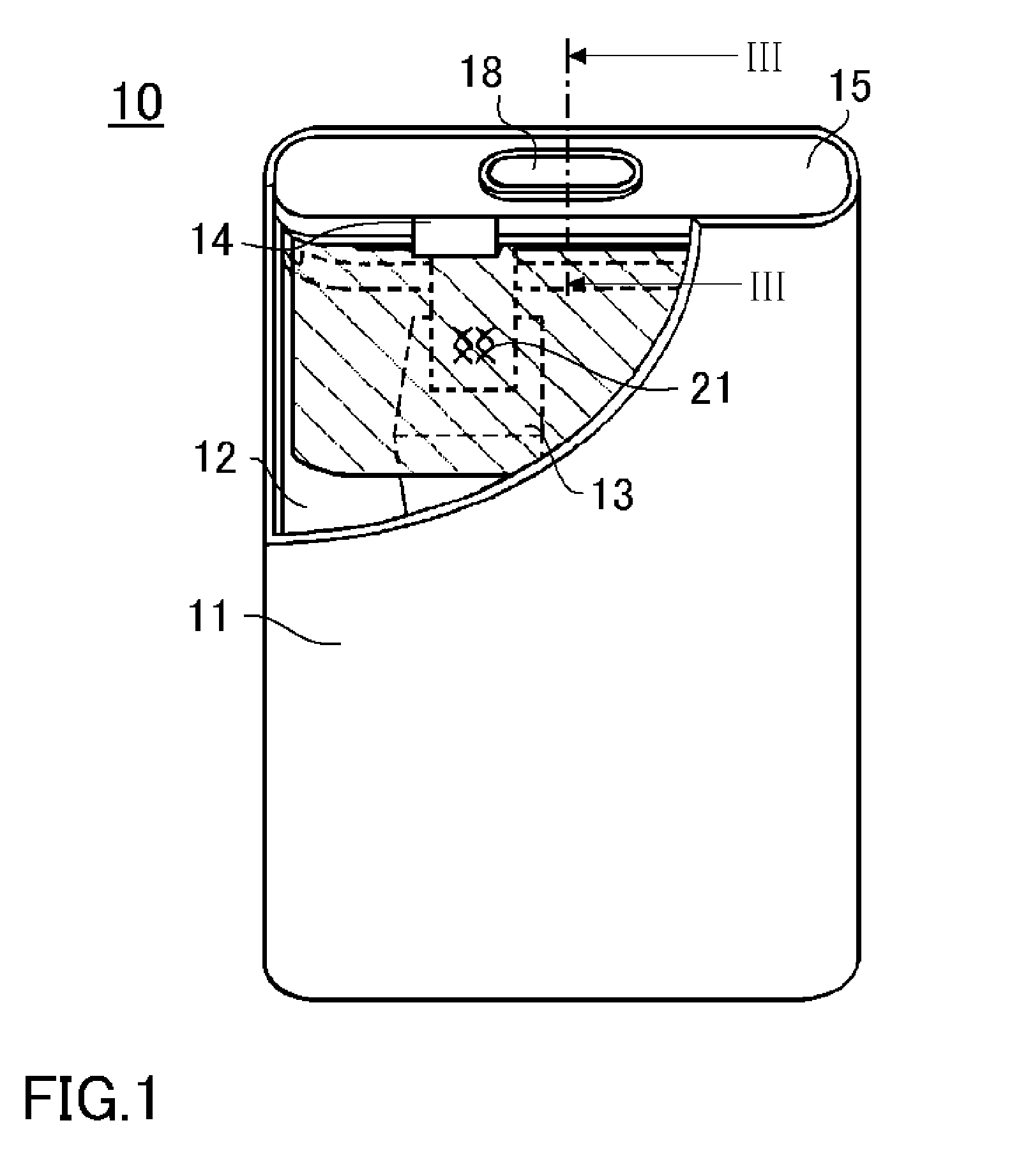
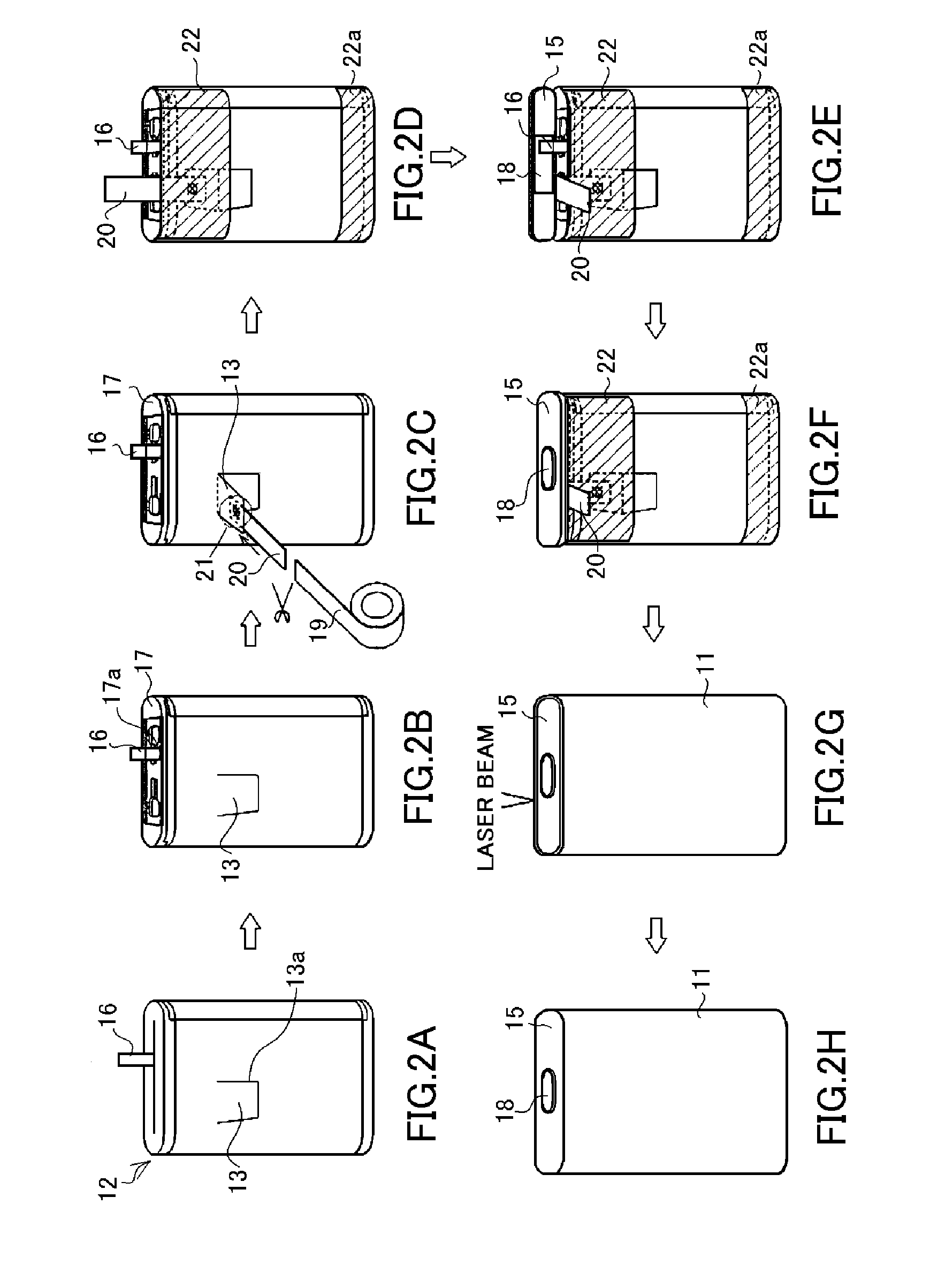
[0037]An embodiment of the invention will now be described with reference to the accompanying drawings. However, it should be understood that the embodiment set forth below, which concerns a compact prismatic nonaqueous electrolyte secondary battery including a terminal for a sealed battery, is intended by way of an example for realizing the technical concepts of the invention, and not by way of limiting the invention to this particular prismatic nonaqueous electrolyte secondary battery. The invention can equally well be applied to nickel-hydrogen secondary batteries and other sealed batteries, or to large-size sealed batteries for HEVs, EVs, and other applications. In addition, although for reasons to do with the structure of a sealed battery, a negative electrode terminal is described below as an example of terminals for a sealed battery according to the invention, the invention applies also to positive electrode terminals in the same way, as well as to negative electrode terminal...


PUM

PropertyMeasurementUnit
heightaaaaaaaaaa
shapeaaaaaaaaaa
circumferenceaaaaaaaaaa

Abstract

A negative electrode terminal includes an outer terminal of a solid flat rivet shape and an inner terminal of a hollow flat rivet shape. A hollow axle portion of the inner terminal is inserted in a first insulating member, an opening bored in a sealing plate, and a second insulating member so as to be insulated from the sealing plate. A columnar axle portion of the outer terminal is inserted into the hollow axle portion of the inner terminal and crimped thereto, so that a radially bulge-deformed portion is formed in an intermediate portion of the columnar axle portion. The hollow axle portion deforms into a shape matching the radially bulge-deformed portion and is crimped to the columnar axle portion, and its tip is curling-formed to match a curved surface between a brim portion and the columnar axle portion of the outer terminal.

Description

TECHNICAL FIELD[0001]The present invention relates to a terminal for a sealed battery including a terminal unit including an outer terminal and an inner terminal, and to a manufacturing method therefor. More particularly, the invention relates to a sealed battery terminal with structure such that the crimped portions between the outer terminal and inner terminal are located on the outside of the battery, so that change in the internal resistance between the outer terminal and inner terminal is suppressed, cost is low, and battery reliability is enhanced; and to a manufacturing method therefor.BACKGROUND ART[0002]With the rapid spread of portable electronic equipment, the specifications required of the batteries used in such equipment have become more demanding year by year. Particularly required are batteries that are compact, thin, high-capacity, superior in cycling characteristics, and stable in performance. In the field of secondary batteries, lithium nonaqueous electrolyte secon...

Claims


Application Information

Patent Timeline
Patent Type & Authority Applications(United States)
IPC IPC(8): H01M2/30H01R43/00H01M50/176H01M50/55H01M50/553H01M50/566
CPCH01M2/30H01M2/0217Y10T29/49218Y10T29/4921H01M2/06H01M10/0525Y02E60/10H01M50/103H01M50/566H01M50/55H01M50/553H01M50/176H01M50/543H01M50/183
Inventor OBAYASHI, ATSUSHIMARUBAYASHI, HIRONORI
Owner SANYO ELECTRIC CO LTD
Why Eureka
Try Eureka